


Nailor Industries Inc. reserves the right to change any information concerning product or pricing without notice.
SCHEDULE TYPE:
PROJECT:
ENGINEER:
CONTRACTOR:
DATE
B SERIES
SUPERSEDES DRAWING NO.
6 - 17 - 20
3000
3 - 13 - 18
D30HQE
Page 2 of 2.
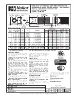
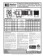
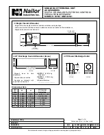
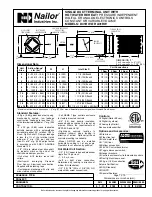
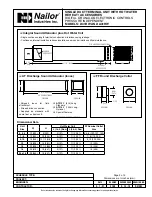
Dimensions are in inches (mm).
SINGLE DUCT TERMINAL UNIT WITH
ELECTRIC REHEAT AND DISSIPATIVE SILENCER
HOSPITAL GRADE • SUPER QUIET
DIGITAL CONTROLS • CONSTANT OR VARIABLE VOLUME
MODEL: D30HQE
Tested and approved
to the following
standards:
ANSI/UL
1996, 1st. ed.
CSA C22.2
No. 155-M1986.
Nailor manufactures its own electric heating coils. They have
been specifically designed and tested for use with variable air
volume single duct terminal units.
All terminals with electric heat have been tested and ETL
listed as an assembly, eliminating the need to mount coils a
minimum of 36" (914) downstream or having to ship a bulky
length of ductwork when coils are to be supplied mounted on
the terminal.
Nailor electric coils are factory mounted as an integral part
of the terminal unit in an insulated extended plenum section.
Total length of the casing including heater terminal is only
31" (787), providing a compact, easy to handle unit. Freight
costs are therefore also reduced. The unique inclined opposed
blade damper design provides improved and more even airflow
over the coil elements compared with round butterfly damper
designs, which helps to minimize air stratification, avoid
nuisance tripping of the thermal cut-outs and maximize heat
pick-up.
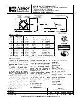
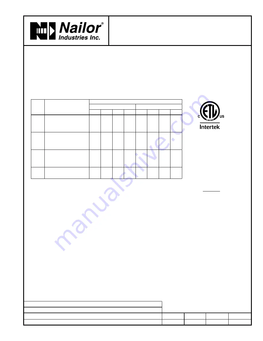
Selection Guidelines:
The table above provides a general guideline as to the
voltages and maximum kilowatts available for each terminal
unit size. Up to three stages of heat are available. A minimum
of 0.5 kW/stage is required.
For optimum diffuser performance and maximum thermal
comfort, ASHRAE recommends that discharge temperatures
do not exceed 15°F (8°C) above room set point, as
stratification and short circuiting may occur. ASHRAE
Standard 62.1 limits discharge temperatures to 90°F (32°C) or
increasing the ventilation rate when heating from the ceiling.
Never select kW to exceed a discharge temperatures of 120°F
(49°C).
ΔT (Air Temp. Rise, °F) =
kW x 3160
cfm
The coils ranges listed are restricted to a maximum of 48
amps and do not require circuit fusing to meet NEC code
requirements. A minimum of .1" w.g. (25 Pa) of downstream
static pressure is required to ensure proper operation of the
heater. To avoid possible nuisance tripping of the thermal
cutouts due to insufficient airflow, a minimum airflow of 70 cfm
(33 l/s) per kilowatt must be maintained.Check that desired
minimum airflow is within recommended operating range.
Standard Features:
• Primary auto-reset high limit thermal
cut-out (one per coil in control circuit).
• Secondary manual reset high limit
thermal cut-outs (one per element).
• Positive pressure air proving switch.
• Class A 80/20 Ni/Cr wire.
• Magnetic contactor per stage.
• Line terminal block.
• High performance arrowhead insulators.
• ETL Listed as an assembly.
• Hinged door control enclosure.
• Slip and drive discharge connection.
Voltage:
Single phase, 60 Hz.
q
120V
q
208V
q
240V
q
277V
q
347V
Three phase, 60 Hz.
q
208V
q
480V
q
600V
q
_____________________ .
Coil Options and Accessories:
q
Toggle type disconnect switch.
q
Door interlock disconnect switch.
q
Mercury contactors.
q
Power circuit fusing.
q
Dust tight construction.
q
SCR control.
q
Special Features:
__________________________ .
Electric Coil Limitations
*
Minimum airflow must be the
greater of the air volume listed or 70
cfm per kilowatt (33 L/s/kW).
Unit
Size
Heating Range*
cfm (l/s)
Maximum kW
Single Phase
Three Phase
120V 208V 240V 277V 347V 208V 480V 600V
4
25 – 225 (12 – 106)
3.0
3.0
3.0
3.0
3.0
3.0
3.0
3.0
5
45 – 400 (21 – 189)
5.0
5.0
5.0
5.0
5.0
5.0
5.0
5.0
6
65 – 550 (31 – 260)
5.5
7.5
7.5
7.5
7.5
7.5
7.5
7.5
7
95 – 800 (45 – 378)
5.5
9.5
9.5
9.5
9.5
9.5
9.5
9.5
8
125 – 1100 (59 – 519)
5.5
9.5
11.0
13.0
13.0
13.0
13.0
13.0
9
165 – 1400 (78 – 661)
5.5
9.5
11.0
13.0
16.0
16.0
16.0
16.0
10
215 – 1840 (101 – 868)
5.5
9.5
11.0
13.0
16.5
17.0
21.0
21.0
12
290 – 2500 (137 – 1180)
5.5
9.5
11.0
13.0
16.5
17.0
30.0
30.0
14
360 – 3125 (170 – 1475)
5.5
9.5
11.0
13.0
16.5
17.0
31.0
38.5
16
430 – 3725 (203 – 1758)
5.5
9.5
11.0
13.0
16.5
17.0
31.0
38.5
24 x 16
960 – 8330 (453 – 3931)
5.5
9.5
11.0
13.0
16.5
17.0
31.0
38.5