


SCHEDULE TYPE
PROJECT
ENGINEER
CONTRACTOR
DATE
B SERIES
SUPERSEDES DRAWING NO.
8 - 3 - 09
3000
5 - 21 - 09
E3001-1
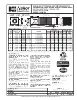
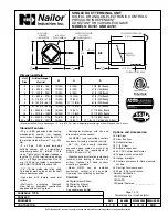
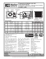
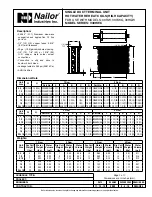
SINGLE DUCT TERMINAL UNIT
ELECTRONIC OR ELECTRIC CONTROLS
PRESSURE DEPENDENT
VARIABLE AIR VOLUME
MODEL: E3001
Nailor Industries Inc. reserves the right to change any information concerning product or pricing without notice.
Page 1 of 2.
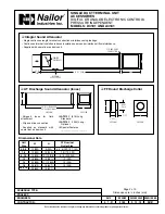
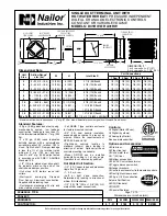
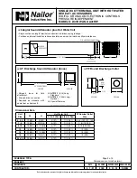
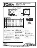
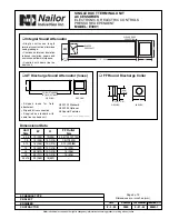
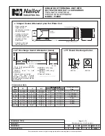
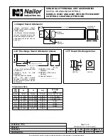
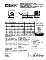
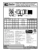
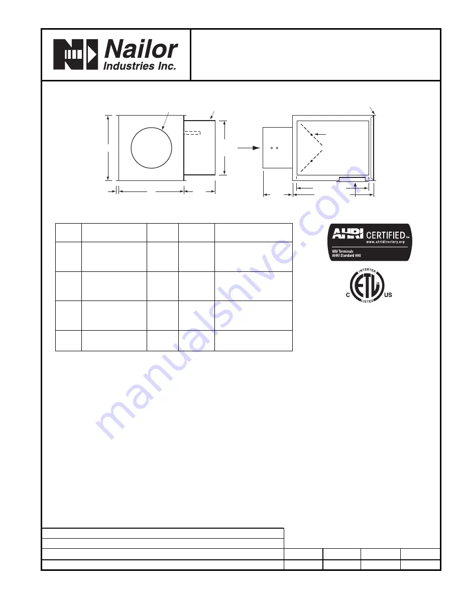
Dimensions are in inches (mm).
W
6"
(152)
11"
(279)
1/2"
(13)
H
AIRFLOW
CONTROLS ENCLOSURE
FOR FACTORY
MOUNTED CONTROLS
INLET: ROUND,
FLAT OVAL OR
RECTANGULAR COLLAR
DAMPER
DRIVESHAFT
SLIP AND DRIVE CONNECTION
15 1/2" (394)
14 1/2" (368)
5 1/2"
(140)
OPTIONAL
ACCESS DOOR
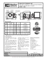
Standard Features:
• 22 ga. (0.86) zinc coated steel casing,
mechanically sealed, low leakage
construction.
• 16 ga. (1.63) corrosion-resistant steel
inclined opposed blade damper with
extruded PVC seals (single blade on
size 4, 5, 6). 45° rotation, CW to close.
Tight close-off. Damper leakage is less
than 2% of the terminal rated airflow at
3" w.g. (750 Pa).
• 1/2" (13) dia. plated steel drive shaft.
An indicator mark on the end of the shaft
shows damper position.
• Rectangular discharge with slip and
drive cleat duct connection.
• Full NEMA 1 type controls enclosure
for factory mounted controls.
• 3/4" (19), dual density insulation,
exposed edges coated to prevent air
erosion. Meets the requirements of
NFPA 90A and UL 181.
• Right-hand controls location is
standard (shown) when looking in
direction of airflow. Optional left hand
controls mounting is available.
Controls:
K
Digital (by others).
K
Analog (by Nailor).
See separate submittal.
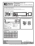
Options and Accessories:
K
Steri-liner.
K
Fiber-free liner.
K
Solid metal liner.
K
1" (25) liner.
K
Bottom access door.
K
24 VAC control transformer.
K
Toggle disconnect switch.
K
Hanger brackets.
K
Controls enclosure for field mounted
controls.
K
Dust tight enclosure seal.
K
Special Features:
_____________ .
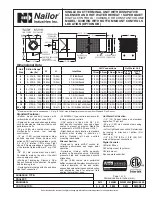
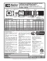
Unit
Airflow Range
W
H
Inlet
Size
cfm (l/s)
Size
4
0 – 180 (0 – 85)
10 (254)
10 (254)
3
7
⁄
8
(98) Round
5
0 – 325 (0 – 153)
10 (254)
10 (254)
4
7
⁄
8
(124) Round
6
0 – 450 (0 – 212)
10 (254)
10 (254)
5
7
⁄
8
(149) Round
7
0 – 650 (0 – 307)
12 (305)
12
1
⁄
2
(318)
6
7
⁄
8
(175) Round
8
0 – 900 (0 – 425)
12 (305)
12
1
⁄
2
(318)
7
7
⁄
8
(200) Round
9
0 – 1150 (0 – 543)
14 (356)
12
1
⁄
2
(318)
8
7
⁄
8
(225) Round
10
0 – 1500 (0 – 708)
14 (356)
12
1
⁄
2
(318)
9
7
⁄
8
(251) Round
12
0 – 2050 (0 – 967)
18 (457)
12
1
⁄
2
(318)
12
15
⁄
16
x 9
13
⁄
16
(329 x 249) Oval
14
0 – 2550 (0 – 1203)
24 (610)
12
1
⁄
2
(318)
16
1
⁄
16
x 9
13
⁄
16
(408 x 249) Oval
16
0 – 3040 (0 – 1435)
28 (711)
12
1
⁄
2
(318)
19
3
⁄
16
x 9
13
⁄
16
(487 x 249) Oval
24 x 16
0 – 6800 (0 – 3209)
38 (965)
18 (457)
23
7
⁄
8
x 15
7
⁄
8
(606 x 403) Rect.
Dimensional Data