North American Clutch & Driveline
Rockford, Illinois
Phone: (800) 383-9204
(815) 282-7960
Fax (815) 282-9160
www.naclutch.com
36
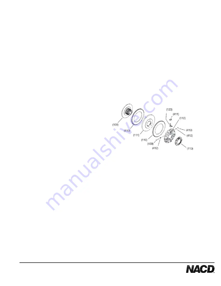
9.4.2 Rotate the adjusting ring (113) counterclockwise to remove it from the clutch
body
Note: Do not disassemble the adjusting ring assembly. If the unit needs to be repaired,
it must be serviced as an assembly. Individual components of the adjusting ring
assembly are not sold separately.
9.5 Complete the disassembly of the clutch.
9.5.1 Lift the pressure plate assembly (112) from the clutch body (109).
9.5.2 Note the direction the clevis pins (409) are installed so they can be reinstalled
in the same direction. Remove retainers (410), washers (412), and clevis pins (409) to
Seperate the levers and lever springs (411) from the pressure plate (112).
10.0 INSPECT THE CLUTCH COMPONENTS
10.1 Clutch Body
10.1.1 Friction surface must not have heat cracks, must be smooth and must be flat
within .005” (.127 mm.).
10.1.2 Splines must not have wear marks exceeding .003” (.076 mm.) depth due to
wear from the pressure plate or center plate.
10.1.3 Keyway must not be worn.
10.1.4 Tapered bore must fit snugly and securely on shaft.
9.5.3 Remove the facing plate (110).
9.5.4 (2 plate and 3 plate clutches only):
Remove the center plate(s)
(111) and the remaining facing plates.
Note: 14” HD(DP) clutches (2 plate) contain
a total of two (2) facing plates and one (1)
center plate. 14" HD (TP) clutches (3 plate)
contain a total of three (3) facing plates and
two (2) center plates.


