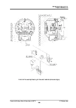
2200LZJE-HO-C6-N_2013.12.
Chapter 5 Maintenance
Compound 2-stage Screw Compressor 2016**C
5.7 Reassembly
5-63
5.7.14 Unloader Indicator
The unloader indicator contains micro-switches, a micro-switch cam and a potentiometer. Either of
them detects the rotational volume change of the shaft of the indicator cam, which converts the axial
positional change of the unloader slide valve into circumferential positional change, and sends it as
electric signals to the control side of the package unit or refrigerating system.
For confirmation after inspection/adjustment or parts replacement, they need to be linked with the
control side. So, even during an overhaul which is conducted with the compressor carried out of the
installation site, this portion is often removed from the compressor as an indicator assembly so that
inspection/adjustment or parts replacement can be conducted at the site.
When removing or inspecting/adjusting the indicator assembly, be sure to turn
off the control power and conduct lockout/tagout. Failure to turn off the power
supply could cause an electric shock.
The 2016**C model has, on its high-stage, an indicator which is designed for the standard-type
single-stage compressor (however, the dial face which is exclusively designed for the 2016**C high-
stage). On the low-stage, it has an indicator designed for the low-stage of 2-stage compressor, which,
additively, has a bevel gear for changing the indicator needle and dial from axial direction to lateral
direction. The basic functions and inspection procedures are common to both. So, the following
explanation is given based on the standard-type high-stage unloader indicator.
5.7.14.1 Micro-switch and Micro-switch Cam
The standard-type unloader indicator has two micro-switches and one micro-switch cam, for sensing
that the unloader slide valve is at the 0% position or the 100% position of capacity control (indicated
load).
If, for any reason, their assembly gets loose or the micro-switch(es) gets faulty, proper sensing will be
disabled, which will cause trouble in operation control of the compressor.
Disassembly
a) Turn off the control power and conduct lockout/tagout. After that, remove the indicator cover
【
146
】
,
indicator glass
【
141
】
and indicator glass spacer
【
142
】
.
b) Remove the indicator needle screw
【
140
】
securing the indicator needle
【
139
】
to the shaft.
c) Remove the indicator dial screws
【
138
】
securing the indicator dial
【
137
】
to the dial supports.
d) Remove the electric wiring of the micro-switch. To avoid future assembly errors, put markings to
indicate positional relationship of wiring by using different colors of tape or the like, and take a note.
e) The micro-switch
【
125
】
is secured with two long philips screws
【
126
】
. The micro-switch can be
removed by loosening these screws. Do not remove these screws except when the micro-switch
needs to be replaced. Leave them as they are when conducting inspections or positional
adjustments.
f) The micro-switch on the right is for sensing the no-load (0%) position and the micro-switch on the
left is for sensing the full-load (100%) position.
Under the left micro-switch, the micro-switch base plate
【
123
】
is secured with different philips
screws
【
124
】
on the micro-switch mounting frame. This is to use the cam which is outside the
micro-switch cam
【
127
】
.
Inspection
a) In a normal state where the compressor's capacity control oil pressure pipe is not opened, pull the
unloader piston to the no-load position/full-load position by using the manual capacity control circuit,
in order to check, through the control circuit (operation check of related relays and/or contacts),
whether the micro-switch senses the 0% /100% position of the micro-switch cam.


