2200LZJE-HO-C6-N_2013.12.
Chapter 5 Maintenance
Compound 2-stage Screw Compressor 2016**C
5.6 Overhaul
5-21
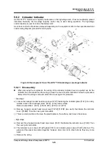
5.6.3 Unloader Cylinder Cover
Unloader cylinder covers
【
74-1
】
【
74-2
】
contain indicator cams
【
77-1
】
【
77-2
】
for converting the
linear position of the unloader slide valve into a rotation angle, as well as parts for attaching the cam.
5.6.3.1 Disassembly
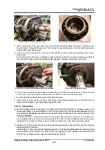
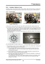
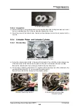
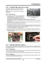
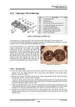
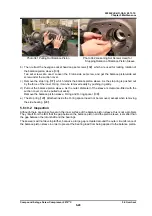
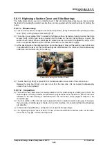
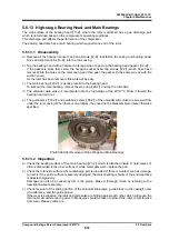
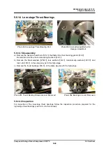
Photo 021 Loosening Bolts of Photo 022 Removing Unloader Cylinder Cover
Unloader Cylinder Cover
a) Remove the hexagon socket head cap screws
【
76
】
used to attach the unloader cylinder cover.
b) The indicator cam
【
77
】
, which is attached to the unloader cylinder cover, is fit to the inner side of
the unloader push rod
【
67
】
which is inside the unloader cylinder. The guide pin
【
68
】
at the tip end
of the push rod is engaged with the groove of the indicator cam. So the unloader cylinder cover can
be pulled out straight as it is (Photo 022).
If the unloader cylinder cover should be bent obliquely, the shaft of the indicator cam will also be
bent. So take care.
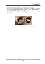
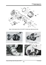
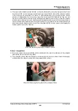
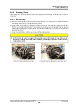
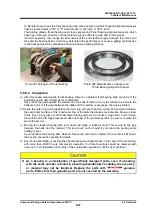
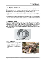
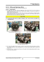
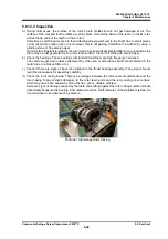
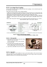
Photo 023 Main Body of Unloader Cylinder Cover Photo 024 Sealed Portion of Indicator Cam
c) If the indicator cam does not move properly, check the groove of the indicator cam, bearings and
guide pin. Disassembly sequence is as shown below.
c-1) The bearing gland
【
80
】
that holds the indicator cam is secured to the cylinder side of the
unloader cylinder cover. Remove the three hexagon socket head cap screws
【
81
】
that are
securing the bearing gland.
c-2) Now, the indicator cam can be pulled out as it is, together (attached to its shaft) with its ball
bearing
【
78
】
and stop ring
【
79
】
securing the bearing.
c-3) The spring retainer
【
84
】
, spring
【
83
】
and Teflon V-rings
【
82
】
are attached, in this sequence,
to the inside of the unloader cylinder cover.
The outer diameter of the Teflon V-rings is attached tightly to the holes of the unloader cylinder
cover. These V-rings, once removed, cannot be reused because their tongue portion gets
damaged. So be careful.

