background image

2200LZJE-HO-C6-N_2013.12. 

Table of Contents 

Compound 2-stage Screw Compressor 2016**C


v


Table of Contents 


Preface .................................................................................................................... 


Revision History ..................................................................................................... 


Warranty and Disclaimer ....................................................................................... 


Important Information ............................................................................................ 


Intended Use of This Product   ........................................................................................... 


Important Information for Safe Use of This Product .......................................................... 


About This Manual ............................................................................................................. 


Construction This Manual .................................................................................................. 


Table of Contents ................................................................................................... 


Chapter 1  Safety  

1.1  Observation/Prevention (DOs and DON'Ts) .............................................. 1-1 

1.1.1 DOs 

...................................................................................................................... 1-1 

1.1.1.1  DOs on Operation ........................................................................................ 1-1 
1.1.1.2  DOs on Maintenance ...................................................................................  1-1 
1.1.1.3  DOs on Lockout/Tagout after Shutting Off the Power ................................. 1-1 
1.1.1.4 DOs 

about 

Personal Protective Gear .......................................................... 1-2 

1.1.1.5  DOs about Handling of Hazardous and Toxic Substances ......................... 1-2 
1.1.1.6 DOs 

about 

Handling Emergency Situations ................................................ 1-2 

1.1.1.7  DOs about Waste Oil, Fluid, and Materials ................................................. 1-2 
1.1.1.8 Other DOs ................................................................................................... 1-2 

1.1.2 

DON'Ts ................................................................................................................ 1-2 

1.2 Warnings 

....................................................................................................... 

1-3 

1.2.1  Types and Meanings of Warnings ....................................................................... 1-3 

1.3 Residual 

Risks 

............................................................................................. 

1-4 

1.4 Safety 

Devices 

.............................................................................................. 

1-6 

1.4.1 Emergency 

Stop Button ....................................................................................... 1-6 

1.4.2  Breakers of motor main power and control power 

(with Lockout/Tagout Mechanism) ...................................................................... 1-6 

1.4.3 Compressor 

Protective Devices .......................................................................... 1-7 


Chapter 2  Configuration and Specifications of Compressor 

2.1  Features of the 


  Compound 2-stage Screw 

Compressor 2016**C .................................................................................... 2-1 

2.2  Model Designation of the Compressor    ................................................... 2-2 

2.3 Compressor 

Specifications 

........................................................................ 

2-2 

2.3.1 Specifications .......................................................................................................  2-2 

2.3.2 Operation 

Limits ...................................................................................................  2-3 

2.3.3 External 

Dimensions ............................................................................................  2-4 


Содержание 2016 C Series

Страница 1: ...SC 2016SSC ATTENTION Before operating servicing or inspecting this product read this manual thoroughly to fully understand the contents Keep this Instruction Manual in a safe designated place for future reference whenever the manual is needed Specifications of this product is subject to change without prior notice ...

Страница 2: ...ore information see 2 2 Model designation of the compressor in this manual Chapter 2 Before installing or using this product make sure you read this manual Keep this manual in a safe place near this product for quick reference Revision History Title Document No First edition issue date 2016 C Instruction Manual 2200LZJE HO C6 N_2013 12 Dec 16 2013 Revision No Issue date Contents of revisions modif...

Страница 3: ...on or damage caused by acts of nature storms heavy rains floods high tides earthquakes subsidences lightnings fires etc Malfunction damage or deterioration caused by misuse or improper use of this product outdoor storage or storage under high temperature and humidity excessively frequent liquid flow back operation extreme start stop repetition etc Malfunction or damage caused by devices or equipme...

Страница 4: ... to avoid danger Do not allow any person other than those educated on the fundamental expertise of this product and trained about hazards involved and measures to avoid dangers to approach this product while it is operating or during maintenance Observe all related federal national and local codes and regulations To prevent accidents do not carry out any operation or maintenance other than those d...

Страница 5: ...sion from MAYEKAWA Photographs or drawings included in this manual may differ from the appearance of actual product If this manual is lost or damaged immediately request our local sales offices or service centers for a new manual Using this product without the manual may result in safety issues If you resell this product never fail to attach this manual to this product Construction of This Manual ...

Страница 6: ...ctive Gear 1 2 1 1 1 5 DOs about Handling of Hazardous and Toxic Substances 1 2 1 1 1 6 DOs about Handling Emergency Situations 1 2 1 1 1 7 DOs about Waste Oil Fluid and Materials 1 2 1 1 1 8 Other DOs 1 2 1 1 2 DON Ts 1 2 1 2 Warnings 1 3 1 2 1 Types and Meanings of Warnings 1 3 1 3 Residual Risks 1 4 1 4 Safety Devices 1 6 1 4 1 Emergency Stop Button 1 6 1 4 2 Breakers of motor main power and co...

Страница 7: ...n 3 5 3 2 5 3 Equipment and Devices for Protection of the Compressor 3 5 3 2 6 Airtightness Test 3 6 3 2 7 Lubricant Charge 3 6 3 2 7 1 Initial Charge of Lubricant 3 6 3 2 7 2 Additional Charge of Lubricant 3 7 3 2 8 Charge of Refrigerant 3 7 3 2 9 Check after Installation 3 7 Chapter 4 Operation of Compressor and Unit 4 1 Lubricant Refrigerant Oil 4 1 4 1 1 Precautions for Selecting the Lubricant...

Страница 8: ...nit 5 10 5 4 5 Removing and Lifting the Compressor 5 11 5 4 6 Removing Oil from Compressor 5 11 5 5 Disassembly Sequence 5 12 5 6 Overhaul 5 14 5 6 1 Mechanical Seal 5 15 5 6 1 1 Disassembly 5 15 5 6 1 2 Inspection 5 16 5 6 2 Unloader Indicator 5 18 5 6 2 1 Disassembly 5 18 5 6 3 Unloader Cylinder Cover 5 21 5 6 3 1 Disassembly 5 21 5 6 3 2 Inspection 5 22 5 6 4 Unloader Piston and Unloader Cylind...

Страница 9: ... 5 6 18 2 Inspection 5 37 5 6 19 Low stage Unloader Slide Valve and Guide Block 5 38 5 6 19 1 Disassembly 5 38 5 6 19 2 Inspection 5 38 5 7 Reassembly 5 39 5 7 1 Low stage Unloader Slide Valve and Guide Block 5 41 5 7 2 High stage Rotor Casing 5 41 5 7 3 Bearing Head and Main Bearings High Low stage 5 42 5 7 4 Bearing Head and Rotor Casing High Low stage 5 43 5 7 5 Attaching Rotors High Low stage ...

Страница 10: ...Assembly Sectional View Horizontal 7 6 Figure 7 7 2016LSC Assembly Sectional View Vertical 7 7 Figure 7 8 2016LSC Assembly Sectional View Horizontal 7 8 Figure 7 9 2016MSC Assembly Sectional View Vertical 7 9 Figure 7 10 2016MSC Assembly Sectional View Horizontal 7 10 Figure 7 11 2016SSC Assembly Sectional View Vertical 7 11 Figure 7 12 2016SSC Assembly Sectional View Horizontal 7 12 7 2 Parts Con...

Страница 11: ... to acknowledge the other worker s movement When troubleshooting during operation or before performing setup cleaning or maintenance inspection of this product always turn OFF the main power to the motor and control power and other devices Also lock and tag out them to prevent the power from being supplied erroneously during operation When troubleshooting during operation or before performing setu...

Страница 12: ...anufacturers of hazardous and toxic substances Check the SDS and follow the handling instructions recommended by the manufacturers to handle and store those substances 1 1 1 6 DOs about Handling Emergency Situations Formulate an emergency action plan complying with the regulations and post it on a safe place 1 1 1 7 DOs about Waste Oil Fluid and Materials Disposing of refrigerant and oil used for ...

Страница 13: ...s manual warn dangerous situations that may arise during work by using the following four categories Neglecting such warnings may cause accidents resulting in personal injury or even death Also this product or its auxiliary equipment may be heavily damaged Therefore be sure to always observe the instructions of the warnings Table 1 1 Types and Meanings of Warnings Indicates a hazardous situation w...

Страница 14: ...eakage or spout of refrigerant or the like Keep away and do not touch Wear protective gear Detect gas leakage Wear protective gear Work at a temperature of not higher than 40 C E Check valves service valves and joints on each section of the unit Contact with or inhalation of hazardous substances generated by mishandling or leakage Frostbite or burn due to contact Sufficient ventilation Indicate va...

Страница 15: ...ZJE HO C6 N_2013 12 Chapter 1 Safety Compound 2 stage Screw Compressor 2016 C 1 3 Residual Risks 1 5 Figure 1 1 Locations of Hazardous Sources compressor Photo 001 Locations of Hazardous Sources A C D A C D ...

Страница 16: ...on Positions On the control board and in the operation control room Stop Restoration Methods For information on how to stop or restore the emergency stop button refer to the instruction manual of the unit Inspection Method Cycle The emergency stop buttons must be tested before commissioning and must also be periodically re tested after that For the inspection method and frequency for the emergency...

Страница 17: ...essure sensing port to the discharge pipe Protecting from intermediate pressure IP This device controls the compressor appropriately when the intermediate pressure exceeds the set value In some cases this device stops the compressor operation Install a pressure output port to the unit s intermediate gas pipe or compressor s intermediate gas pressure output port Protecting from suction pressure dro...

Страница 18: ...Compressor protective devices require operation tests and confirmation of the settings calibration before test run as well as at regular intervals For information on inspecting procedure and frequency for the compressor refer to the instruction manual of the unit In the operation test check that alarms and protective devices operate normally by using devices such as pressure tester Do not operate ...

Страница 19: ... 2 stage screw compressor is produced to solve this problem It is a single unit that has two single stage compressor units combined into one The 2016 C model has a capacity control mechanism for startup load reduction on the high stage and a capacity control mechanism for coping with load change on the low stage There are various combinations of machine control methods capacity control methods How...

Страница 20: ...gerant NH3 HFC etc Design pressure MPa 2 6 Capacity control Actual load 10 to 100 Rotation direction Counterclockwise viewed from motor Connected pipe size Low stage suction flange JIS 20K 150A 6 Low stage discharge flange JIS 20K 100A 4 High stage suction flange JIS 20K 100A 4 High stage discharge flange JIS 20K 80A 3 Journal lubrication low stage JIS 20K 25A 1 Journal lubrication high stage JIS ...

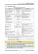
Страница 21: ...en rotor and casing Maximum oil supply temperature 60 C Oil viscosity should be not less than 13mm2 s Optimally oil viscosity should be between 13 and 40 mm2 s Minimum oil supply temperature 30 C Oil viscosity should be not higher than 60mm2 s Maximum M rotor rotation speed 4000 rpm Bearing inherent properties seal Minimum M rotor rotation speed 1450 rpm Bearing Note 1 Unless otherwise noted the p...

Страница 22: ...E HO C6 N_2013 12 Chapter 2 Configuration and Specifications of Compressor Compound 2 stage Screw Compressor 2016 C 2 3 Compressor Specifications 2 4 2 3 3 Outer Dimensions Figure 2 1 Outer Dimensions 2016LLC ...

Страница 23: ...2200LZJE HO C6 N_2013 12 Chapter 2 Configuration and Specifications of Compressor Compound 2 stage Screw Compressor 2016 C 2 3 Compressor Specifications 2 5 Figure 2 2 Outer Dimensions 2016LMC ...

Страница 24: ...2200LZJE HO C6 N_2013 12 Chapter 2 Configuration and Specifications of Compressor Compound 2 stage Screw Compressor 2016 C 2 3 Compressor Specifications 2 6 Figure 2 3 Outer Dimensions 2016LSC ...

Страница 25: ...2200LZJE HO C6 N_2013 12 Chapter 2 Configuration and Specifications of Compressor Compound 2 stage Screw Compressor 2016 C 2 3 Compressor Specifications 2 7 Figure 2 4 Outer Dimensions 2016MSC ...

Страница 26: ...2200LZJE HO C6 N_2013 12 Chapter 2 Configuration and Specifications of Compressor Compound 2 stage Screw Compressor 2016 C 2 3 Compressor Specifications 2 8 Figure 2 5 Outer Dimensions 2016SSC ...

Страница 27: ...e two screw rotors are a set of a male rotor having 4 protruding tooth profiles M rotor and a female rotor having 6 concave profiles F rotor They conduct compressing according to the mechanism explained below The standard compressor s M rotor is driven by a 2 pole motor it operates at 3000 rpm 50 Hz or 3600 rpm 60 Hz F rotor operates at 2000 rpm 50 Hz or 2400 rpm 60 Hz conforming to the operation ...

Страница 28: ...aving 4 protruding tooth profiles is called a male or M rotor and the rotor having 6 concave profiles is called a female or F rotor In this manual they are referred to as M rotor and F rotor The compressor is driven by the motor connected to the shaft of the M rotor Figure 2 7 Compressor Mechanism 2 5 2 Suction Process As shown in Figure 2 8 the rotors with different tooth profiles are engaged As ...

Страница 29: ... is as follows L 2 63 M 3 65 H 5 80 Volume of suctioned refrigerant gas immediately before the start of compression Vi Volume of refrigerant gas just before pushed out to discharge port Which volume ratio L M or H should be used is decided according to operating conditions If the compressor is used with a volume ratio that does not match operating conditions operation will go inefficiently wasting...

Страница 30: ...pression Change in volume enclosed by tooth profiles Internal pressure Internal pressure Low Vi conditions High Vi conditions Rotor rotation angle Rotor rotation angle Suction port closed Suction port closed Discharge port opened Discharge port opened Change in volume enclosed by tooth profiles Change in volume enclosed by tooth profiles Suction Suction Compression Discharge Compression Discharge ...

Страница 31: ...of angular contact ball bearings are used Special care is taken to cope with the load acting along the shaft direction Because the M rotor is a kind of helical gear and also because the thrust force produced by discharge pressure is larger than that for F rotor the load applied onto the M rotor is reduced by using not only a thrust bearing but also a balance piston that applies pressure from the o...

Страница 32: ...discharged from 6 and is sent from the oil separator to the condenser Even if without intermediate gas cooling oil provides cooling effect So the high stage discharge temperature is maintained at a temperature not higher than 90 C Oil Supply Mechanism As shown in Figure 2 16 lubricant is split into five flows After completing each role the oil is mixed with discharge gas and leaves the compressor ...

Страница 33: ...g Check that there are no abnormalities such as damage on the compressor If there are abnormalities or deficient parts on the compressor please contact our sales offices or service centers immediately Unnecessary packing materials should be discarded according to the laws and ordinances or your company s rules 3 2 2 Storage Perform the followings to store the compressor before installation Store i...

Страница 34: ...from the ground Check that the compressor is not tilted If the compressor is tilted return the compressor to the ground and correct the tilt by adjusting the wire ropes After that restart the lifting operation 11 Be sure to lift up the compressor slowly If it is lifted rapidly it may damage the lifting tools such as wire ropes or a part of the compressor 12 When the lifting work starts observe to ...

Страница 35: ...6 C 3 2 Installation Works 3 3 Outer Dimensions Weight and Lifting Position 2016LLC 2016LMC 2016LSC 2016MSC 2016SSC Weight kg 1180 1140 1100 1050 1000 L mm 1980 5 1913 5 1842 5 1787 5 1730 5 Figure 3 1 Outer Dimensions Weight and Lifting Position of Compressor Photo 002 Lifting Position ...

Страница 36: ...gure 3 2 High stage gas inlet JIS 20K 100A 4 See Figure 3 2 High stage discharge gas outlet JIS 20K 80A 3 See Figure 3 2 Lubrication oil supply port for low stage bearing journal JIS 20K 25A 1 Lubrication oil supply port for low stage capacity control increased side Rc1 4 Lubrication oil supply port for low stage capacity control decreased side Rc3 8 Oil supply port for oil injection JIS 20K 15A 1...

Страница 37: ...onnection ports Improper piping may cause operating problems such as oil not returning to the compressor or liquid flow backs When connecting the piping to the compressor use piping that is the same size as the compressor connection port If the pipe size of the piping is smaller than the compressor connection port the flow of lubricant or refrigerant will be obstructed leading to problems Do not l...

Страница 38: ...e the unloader cylinders 2 Close the oil separator outlet valve in the oil supply line Also close the oil injection adjusting valve 3 Charge lubricant from the drain valve on the oil cooler or the drain valve on the oil filter 4 When the oil level reaches the lower limit of the oil level gauge of the oil separator finish supplying lubrication oil from the oil line Minimum amount to be charged of l...

Страница 39: ...d amount of initial charge of lubricant refer to the instruction manual of the unit 3 2 7 2 Additional Charge of Lubricant For additional charge of lubricant during operation the procedures of charging defer depending on the systems and operating conditions therefore follow the procedures described in the instruction manual of the unit 3 2 8 Charge of Refrigerant Charge refrigerant by referring to...

Страница 40: ...ter soluble the viscosity of the oil drops to a level remarkably below the level required for operation of the compressor under some operating conditions On the contrary if the refrigerant does not dissolve in the oil or the oil and refrigerant are non inter soluble the viscosity may become too high when the supply oil temperature is low For this reason the lubricant must be selected such that it ...

Страница 41: ...68 Kluber REFLO XL 59 Petro Canada Synthetic oils non inter soluble oils Brand Kinematic viscosity 40 C mm2 s Manufacturer Type Acemire 300 59 Acemire AB Mycold AB68 53 BVA ZERICE S46 46 Exxon Mobil ZERICE S68 68 Exxon Mobil BERREL FREEZE 46S 46 Matsumura Oil Co Ltd CP 4700 32 31 CPI CP 4700 68 56 CPI Gold Cold 300 53 Golden West GARGOYLE ARCTIC NH68 64 Exxon Mobil PAO AB REFLO SYNTHETIC 68A 62 Pe...

Страница 42: ...from the compressor as well as from the condenser evaporator and all other refrigerating unit components before charging the new lubricant After 100 to 200 hours of operation replace the oil again If lubricant manufacturers differ contact both of them and inquire whether the changing is appropriate The same confirmation is required for changing the brand even if it is of the same manufacturer Ther...

Страница 43: ...rrosion or corrosive wear So pay attention especially to the following Charge oil as quickly as possible after opening the pail can within 15 min if possible Avoid replenishing oil on a rainy day or when the workplace is humid to prevent absorption of moisture Do not use the oil that is left in the container after charge If JOMO Freol PN46 drops on a painted surface wipe it off as quickly as possi...

Страница 44: ...or at least 15 minutes Check the condensing pressure by using the pressure gauge of the compressor 2 Check the cooling water temperature 3 Compare the condensing pressure checked in step 1 above with the refrigerant saturation pressure that depends on the cooling water temperature as shown in the table below Table 4 1 Typical Refrigerant Temperature and Saturation Pressure Unless otherwise noted t...

Страница 45: ...operation stop period is 1 month or longer perform the following checks once per month Measure the system pressure Check for refrigerant leak Operate the oil pump for 5 minutes After that rotate the compressor shaft 10 rotations or more When restarting the compressor after an operation stop period of 1 year or longer check the system for refrigerant leak and replace the refrigerant oil Also check ...

Страница 46: ...ny of its parts without prior permission of Mayekawa It may cause the compressor to be damaged or disabled from maintaining its normal functions When disassembling the compressor remove it from the unit frame and place it on a work bench Before removing the compressor from the unit frame recover the refrigerant from the unit properly and check that the pressure inside the compressor is atmospheric...

Страница 47: ... periodic maintenance timing Suction pressure MPa Note 1 Difference from the set value of evaporation temperature equivalent pressure Contamination on the cooling pipe surface Temperature flow rate etc of the object to be cooled Intermediate pressure MPa Pressure difference from rated operation normal value If it is too large check high stage If it is too small check low stage Discharge pressure M...

Страница 48: ...lace the oil filter At the beginning of the operation the differential pressure of the oil filter may increase quickly 3 Cleaning of suction strainer When the compressor operating hours exceeds 500 check the suction strainer If a temporary filter is installed for the initial stage of operation remove it At the beginning of the operation or after periodical check the differential pressure between t...

Страница 49: ...ration Analyze oil every 6 months When the analysis results do not meet the management criteria provided in 5 3 Management of Lubricant of this manual replace oil Oil filter Replace once per year Replace oil filter when the differential pressure between the discharge pressure and oil supply pressure exceeds 0 15 MPa Cooling water side of oil cooler Check once per year Clean if excessively contamin...

Страница 50: ...ndition Application example Recommended Overhaul Frequency Relatively stable operating condition Cold storage and refrigeration Every 5 years or 40 000 operating hours Relatively changing operating condition Ice maker chiller Every 4 years or 30 000 operating hours Frequently started stopped and relatively changing operating conditions Heat pump Every 3 years or 20 000 operating hours Note 1 The a...

Страница 51: ... level Max 15 mg 100 ml as measured by gravimetric Millipore filter method Note2 Table 5 6 Mineral Oils and Synthetic Oils AB PAO Item Management Criteria a Color ASTM color standard 6 0 or less b Total acid number TAN Max 0 3 mg KOH g c Kinematic viscosity Within 15 in variation when compared with fresh oil d Water content Max 100 ppm Note 1 e Contamination level Max 15 mg 100 ml as measured by g...

Страница 52: ...o not meet the management criteria for each oil type detailed in Tables 5 5 through 5 7 replace the lubricant 5 3 2 2 During regular operation Lubricant deteriorates gradually as the system is operated over time The deterioration rate depends on the operating conditions oil type and any foreign substances or water in the oil Sample and analyze the lubricant every 6 months and if the results do not...

Страница 53: ... Numbers denoted by that follow part names refer to the numbers used in assembly cross section views or development views Before starting inspection maintenance be sure to cut off the main power supply and control power supply Be careful that the power will not be turned on during inspection maintenance If the power is turned on during inspection maintenance the compressor or oil pump may start mo...

Страница 54: ...to be damaged replace all with new ones When purchasing any part inform its a model b serial number c part name d code No and e necessary number to our sales office or service center Especially when the b serial number of the compressor is not identified it will be difficult to decide the required parts because we can not specify the design and manufacturing specifications 5 4 3 Recovering the Ref...

Страница 55: ... and the intermediate inter unit pipe connecting low stage discharge port and high stage suction port 3 Compressor s lubrication piping journal lubrication 2 sets oil injection 1 set and capacity control increase decrease 2 sets for each 4 Electric wiring for operating capacity control Depending on the situation of the workplace unloader indicator assembly may be used See 5 7 14 Unloader Indicator...

Страница 56: ... steps and when performing work steps and onwards see Figure 5 1 Illustrated Disassembly Sequence in 5 5 of this chapter do not disassemble while lifting the compressor put the compressor on a table as shown in Photo 004 below and remove approximately 8 bolts from the lower side of the flange as necessary These bolts cannot be removed after the compressor is brought down on the work bench Photo 00...

Страница 57: ...e work bench When conducting steps through the compressor should be removed from its frame and placed on a work bench prepared in advance When disassembling high stage or low stage side only start from step and disassemble necessary parts only Parts which have no problem should be left as they are Do not disassemble such parts unless during periodical inspection Since it is difficult to completely...

Страница 58: ...2200LZJE HO C6 N_2013 12 Chapter 5 Maintenance Compound 2 stage Screw Compressor 2016 C 5 5 Disassembly Sequence 5 13 Figure 5 1 Illustrated Disassembly Sequence ...

Страница 59: ...There is a risk that the compressor s main body or parts may drop on human body When using a crane allow only qualified personnel to operate it Entrusting the work to unqualified personnel may result in fall accident Replace the parts with genuine parts If parts other than genuine parts are used there is a risk of the compressor and equipment being damaged or ruptured For compressor disassembly as...

Страница 60: ... b Loosen the remaining two screws alternately and evenly a little at a time After loosened to some extent the seal cover of the mechanical seal will be raised slightly by the force of the inside spring creating a gap under the cover The gap will not be created if the gasket is sticking to both surfaces In this case free the cover by screwing the 8 mm eye bolts into the forcing screw holes in the ...

Страница 61: ...rews pull out the oil seal sleeve j Screw two eye bolts into the jacking screw holes in the oil seal retainer and pull out the oil seal retainer while keeping it at a right angle against the shaft 5 6 1 2 Inspection a Mechanical seal should be replaced if any defect is found during inspection Actually however it is sometimes difficult to find out defects on the sliding surface only through visual ...

Страница 62: ...l seal 50 and oil seal sleeve 528 with new parts Since the oil seal is made of a special material only a genuine oil seal must be used for replacement About the O rings attached to oil seal sleeve 744 In the design madification applied in March 2010 O ring 744 is attached to the inner diameter of the oil seal sleeve d Replace the seal cover gasket with a new one Photo 010 Oil Seal Retainer and Oil...

Страница 63: ...tor has a terminal board for wiring remove the cover from the indicator Follow the procedure below After the wiring is removed attach the cover again for protection Low stage a Loosen the hexagon socket head cap screws 212 fastening the indicator glass 141 Do not by mistake loosen the crosshead screw 210 on the same surface Remove assemblies 141 202 to 207 210 and 211 b Remove hexagon socket head ...

Страница 64: ...verhaul 5 19 Figure 5 4 Development View of the 2016 C Standard type High stage Indicator Photo 011 Removing Low stage Indicator Cover Photo 012 Loosening Low stage Micro switch Cam Set Screw Photo 013 Removing High stage Indicator Cover Photo 014 Loosening High stage Micro switch Cam Set Screw ...

Страница 65: ...l potentiometer ii micro switch and iii micro switch base plate 121 attached with micro switch cam get removable b Remove hexagon socket head cap screws 122 c Loosen the micro switch cam set screw 128 d Now the assembly can be pulled out as it is if pulled out in the axial direction Photo 015 Loosening the Screws Photo 016 Removing High stage Indicator Securing High stage Micro switch Base Plate P...

Страница 66: ...t is Photo 022 If the unloader cylinder cover should be bent obliquely the shaft of the indicator cam will also be bent So take care Photo 023 Main Body of Unloader Cylinder Cover Photo 024 Sealed Portion of Indicator Cam c If the indicator cam does not move properly check the groove of the indicator cam bearings and guide pin Disassembly sequence is as shown below c 1 The bearing gland 80 that ho...

Страница 67: ... Piston and Unloader Cylinder 5 6 4 1 Disassembly Photo 026 Disengaging the Lock Washer Claw a Pull out the unloader piston 64 to the utmost front position Then lift off the rotation stopper claw of the lock washer 70 that secures the piston to the push rod and loosen the lock nut 69 Remove the unloader piston by screwing eye bolts into the two screw holes b The low stage unloader cylinder 60 1 is...

Страница 68: ...nloader cylinder can be removed as a unit combined with the balance piston cover At this moment there is oil accumulated at the balance piston and side bearings So pay attention to the oil that will flow out when removing the balance piston cover When the gasket 23 is stuck remove it by tapping the balance piston cover with a hammer Photo 029 Removing High stage Unloader Cylinder 5 6 4 2 Inspectio...

Страница 69: ...provided in symmetric positions Screw the two bolts that have been removed 18 1 into the right and left holes This will cause the bearing cover to separate from the bearing head When a small gap is created peel up one side of the gasket 17 1 by using a thin knife or a spatula shaped tool c Screw the bolts further until the cover comes off the alignment pins At this time be sure to support the bear...

Страница 70: ... by gasket 17 2 Tap the suction cover at its leg portion or screw in screws 18 2 which have been removed into the holes on the bearing head to separate the suction cover evenly by pushing Do not drive a screwdriver or chisel into the gap d The power transmission gear couplings 151 to 161 are attached to the inside of M rotor shaft Move the main body in parallel with the shaft to separate the drive...

Страница 71: ...fter that remove the thrust washer 250 2 torsional slip washer 237 2 and lock nut 39 2 b Remove the hexagon head bolt 45 2 and its conical spring washer 46 2 holding the thrust bearing gland 43 2 and then remove the gland In case of a former model which uses a rotation stopper fitting instead of a conical spring washer extend the claw of the rotation stopper and remove it from the hexagon head blo...

Страница 72: ...e there is a problem b Rotate the outer ring while supporting the inner ring with your hand If you feel an abnormal vibration the ball contact surface of the inner outer ring or the balls themselves are defective Make a closer check Even a tiny piece of dirt that entered during removal can cause a rough feel In such case blow off the dirt with high pressure air after cleaning If the problem persis...

Страница 73: ... upper side While holding down the balance piston cover remove the remaining screw and remove the balance piston cover 5 6 10 Balance Piston When the screw compressor is operated the thrust load applied to the M rotor is large and the M rotor rotates very fast compared with the F rotor Therefore the life of thrust bearing on the M rotor would normally be much shorter than that of those attached on...

Страница 74: ...ily by pushing in gently d Pull out the balance piston sleeve As the outer diameter of the sleeve is clearance fitted with the suction cover it can be pulled out easily Remove the balance piston sleeve O ring and O ring spacer 36 e The stop ring 29 attached inside the O ring spacer need not be removed except when removing the side bearing 28 5 6 10 2 Inspection Although there are signs of wear on ...

Страница 75: ...ver all at once in parallel with the axis As the thrust bearings are disconnected the rotors will be simultaneously pulled out Let the rotors stay in the casing Photo 043 Pulling Out Suction Cover d The side bearing 28 2 is press fit from the balance piston cover side of the suction cover Release the stop ring 29 2 and push it out from the rotor side It is not subject to disassembly unless it has ...

Страница 76: ...rotating it clockwise When approximately two thirds of the rotor has been pulled out draw the rest out slowly while attaching the other hand to the outer circumference of the rotor If you pull out the M rotor without rotating it the F rotor will also be pulled out simultaneously Photo 044 Before Pulling Out Rotors Photo 045 Pulling Out M Rotor Photo 046 Pulling Out F Rotor b Do not place the pulle...

Страница 77: ...ace Clean it off softly with emery paper b Check the bearings These bearings of standard machines are high frequency hardened They scarcely get worn unless extremely dirty oil is used or hard pieces of dirt are embedded in the metal due to a broken filter etc c Check if there are signs of inner race rotation in the thrust bearing assembly If any sign is found read the precautions for assembly care...

Страница 78: ... the rotor side d The unloader slide valve is incorporated into the high stage of the 2016 C Draw it toward the bearing head and out e The guide block 87 2 and guide block stem 88 2 of the unloader slide valve are screwed from under the rotor casing When there is no problem they need not be disassembled unless otherwise specified Photo 048 After Removal of Stop Rings and Main Bearings 5 6 13 2 Ins...

Страница 79: ...s 43 1 Be careful not to lose the conical spring washers 46 1 b Remove the thrust washers 250 1 lock washers 40 1 torsional slip washers 237 1 and lock nuts 39 1 in the same way as for the high stage c Remove the thrust bearings 38 1 in the same way as with the high stage Photo 051 Thrust Bearing Glands are Just Removed Photo 052 Bearings are Just Removed 5 6 14 2 Inspection For inspection of the ...

Страница 80: ...er inside the sleeve compatible with the former method Date on which design was changed The new method was applied first to assembly in oct 19 2010 Model N2016SSC LBM Serial number 2023130 5 6 15 1 Disassembly a Driven sleeve 151 can be removed with hands Remove the drive hub 152 Lift off the lock washer 161 claw and loosen the lock nut 160 b Two screw holes are provided on the drive hub Screw in ...

Страница 81: ... screws 2 1 Then drive alignment pins 3 1 into the rotor casing 1 1 f Screw hexagon socket head cap screws 2 1 into the two screw holes on the rotor casing flange to push the suction cover flange evenly g When a gap is created peel up the gasket by using a knife or a spatula Attach it to the suction cover h When a gap gets spread to a full length of the screws release the engagement of the rotor s...

Страница 82: ...earing head 11 1 and rotor casing 1 1 need not be separated except when overhauling the unloader slide valve To separate them follow procedure steps a to d in 5 6 18 1 below 5 6 18 1 Disassembly a Remove all the hexagon socket head cap screws 2 1 b Drive an alignment pins 3 1 into the rotor casing flange c Separate the bearing head and rotor casing by using the screw holes in the flange d Since th...

Страница 83: ...oader Slide Valve Photo 059 Unloader Slide Valve and Guide Block 5 6 19 1 Disassembly a If pulled in the discharge direction the push rod 67 1 can be removed easily b When replacing the push rod remove the hexagon socket head cap screw 162 c The oil injection pipe guide 168 is fastened from inside by using lock nut Pull out the hexagon socket head cap screws 58 1 and washers 267 1 to disassemble t...

Страница 84: ...acement can lead to defects such as oil leakage Some gaskets are asymmetrical In that case ensure that the assembly direction is correct If the assembly direction is not correct problems such as blocking of oil passages machined in the casing may occur resulting in serious defects Start assembly when disassembly and inspection are finished Recheck the purchased replacement parts before assembly Re...

Страница 85: ... Chapter 5 Maintenance Compound 2 stage Screw Compressor 2016 C 5 7 Reassembly 5 40 Figure 5 7 Illustrated Assembly Sequence The circled numbers in the figure do not correspond to the paragraph numbers used in the steps below ...

Страница 86: ... and move it several times to check its movement Inspect the joint with the casing and confirm that there is no unevenness Since unevenness indicates improper assembly reassemble it again If used without correcting it the outer periphery of the rotor may hit against the slide valve causing an unexpected accident Regarding the unevenness between the unloader slide valve and the casing there is no p...

Страница 87: ...uch a way that it aligns with the spring pin 14 which is screwed into the bearing head use of a jig like the guide rod shown in Photo 062 is helpful After that pad the bearing and drive it If misaligned pull it out once and then assemble it again When press fitting using a weight jig and a plastic spacer indicated in the Figure 5 8 makes attaching bearing works easier The plastic spacer should be ...

Страница 88: ...xt drive in the alignment pins 3 1 to fix the position and then screw bolts in opposing positions and then fasten the bolts evenly in turn c After fastening the bolts check that the bearing head gasket is not protruding toward the inside of the casing New gaskets always protrude toward the inside of the casing Cut the protruded portion with a sharp knife d Assemble the high stage side in the same ...

Страница 89: ... the alignment when attaching to the rotor casing numbers are stamped on the discharge side tooth peak of the M rotor and the suction side tooth peak of the F rotor respectively Photo 066 M Rotor Mating Mark Photo 067 F Rotor Mating Marks a Sufficiently lubricate the main bearing inside the bearing head as well as the bearing portion of the rotor shaft b In assembly attach the F rotor first to the...

Страница 90: ... finished secure the side bearing by using the stop ring Photo 071 On the high stage too when the side bearing has been attached secure it by using the stop ring 29 Photo 070 Attaching Side Bearing Photo 071 Securing with Stop Ring Low stage Low stage b After that attach the balance piston to the high stage only by following the procedure below After attaching the stop ring 37 for O ring spacer at...

Страница 91: ...g Balance Piston Sleeve Photo 077 Screwing Set Screws for Stopping Rotation Photo 078 Two Set Screws Have Been Screwed Photo 079 Attaching Stop Ring c The suction cover gaskets 6 1 6 2 are not formed symmetric laterally Thoroughly check the position of the drilled hole for supply oil Lubricate the side bearing sufficiently Photo 080 Assembling Low stage Suction Cover Photo 081 Assembling High stag...

Страница 92: ...al table which was used during disassembly g Rotate the M rotor shaft with your hand and check the rotors mating condition h For the low stage attach the oil injection pipe 85 and then fasten it by using the oil injection pipe retainer 164 Photo 082 Driving In Alignment Pin for Positioning Photo 083 Oil Injection Pipe Retainer i Move the push rod with your hand and check the movement of the unload...

Страница 93: ...sembly This is essential to control the end clearance of the rotor discharge side Even when assembling the same bearing dimensions may become incorrect if flakes of paint or dirt are caught between spacers and alignment spacers Regarding the direction of thrust bearing assembly there may or may not be a V shaped mark for assembly on the outer periphery of the bearing Follow the instructions below ...

Страница 94: ...ctured within standard values Therefore fully tightening the nut from the initial use may lead to a noticeable reduction in the life of bearing due to a lack of end clearance between the rotor and the bearing head discharge end face and also due to indentations on the contact surface formed by ball pressure To avoid this check for end clearance while tightening 5 7 7 1 End Clearance Measurement At...

Страница 95: ...Attach a dial gauge to the edge of the shaft and match the needle to 0 Dial gauge should be attached to the position near the side bearing as shown in Photo 090 in order to make the bearing gland tightening work easier and precise Figure 5 10 End Clearance Adjustment Ⅰ c Fasten the bearing gland by tightening the four bolts without conical spring washer inserted evenly and gradually to the specifi...

Страница 96: ...the shim material is used between thrust bearing alignment spacer and thrust bearing inner race Or if the shim material is not used between thrust bearing alignment spacer and thrust bearing inner race or even if used but insufficient thickness grind the surface of thrust bearing alignment spacer 42 by the difference between the measured value and the specified value or ask professional vendors to...

Страница 97: ...bolts into two of the upper holes provided in the flange surface of the bearing head 1 11 1 c Apply oil to the bearing head flange surface and the both surfaces of the bearing cover gasket 1 17 1 Hang the gasket on those stud bolts in such that it is put on the flange surface d Attach O ring 197 to the part where the pushrod goes through bearing cover 16 e Attach lifting tools to the eye bolt of t...

Страница 98: ... 157 This set screw is knurled and provided with anti loosening b On the low stage attach the drive hub 152 lock washer 161 and lock nut 160 in this order Fasten the lock nut with the specified torque or tightening angle range see Chapter 7 7 3 Tightening Torques for Bolts and Nuts in this manual Align the lock washer claw with the notch of the lock nut and bend it c Set the driven sleeve onto the...

Страница 99: ...llel with the rotor shaft For both upper and lower sides gradually and evenly tighten temporarily the hexagon socket head cap screws 18 2 that are set in the bolt holes each hole located one hole apart from the left or right alignment pin until the high stage and low stage flange surfaces come into contact h After the flange surfaces come into contact slightly loosen the four hexagon socket head c...

Страница 100: ...ed to the current position indicated in photo101 At the same time the same design modification was applied to low stage bearing cover Refer to the next article 5 7 11 in this chapter Photo 100 b Align the balance piston cover with the unloader cylinder A gasket cannot be inserted between the aligning flange surfaces of the balance piston cover and unloader cylinder So as shown in Photo 101 thinly ...

Страница 101: ...having threaded holes faced to the unloader cylinder cover After attaching check that the cap seal is not broken or pinched Photo 104 Photo 105 First Fit in Photo 106 Reverse Direction h Push the unloader piston into around the midst of the unloader cylinder With the unloader push rod 67 2 pulled toward you attach the balance piston cover with gasket attached as shown in Photo 106 onto the high st...

Страница 102: ...ttached b Attach the O ring 65 and cap seal 66 to the unloader piston 64 1 c Attach the unloader piston which has the O ring and cap seal attached to the unloader cylinder 60 1 Photo 111 d Attach the O ring to the O ring groove provided on the portion of the bearing cover 16 where the unloader cylinder is to be attached Photo 112 According to the design change on October 1996 the place O ring 63 i...

Страница 103: ...the specified torque of 120 N m Photo 114 To stop rotation align the lock washer claw with the notch of the lock nut in the tightening direction and bend the claw Photo 115 Lastly check the movement of the unloader piston by using eye bolts Photo 114 Photo 115 For the 2016MSC be sure to attach the spacer for the unloader piston 423 and the O ring 702 to the low stage see Chapter 7 Figure 7 9 in th...

Страница 104: ...al attachment direction has been changed from facing the atmosphere side to facing the opposite side The purpose of this change is to improve oil flow from inside the seal box so that the pressure will not rise too high However in rare cases assembling the oil seal retainer becomes difficult in the following work Then the previous attaching direction is allowed to be used Place a Teflon or other k...

Страница 105: ...t by using two set screws 529 Photo 118 Photo 117 Photo 118 g Then insert the O ring 49 for the oil seal retainer Photo 119 Take special care because users frequently omit to insert the O ring 49 for oil seal retainer h Attach the seal collar 109 which has the O ring 112 attached to its inner periphery to the rotor shaft Before assembly apply sufficient lubricant prepared for use during assembly t...

Страница 106: ...d the mating ring sliding surface will come into contact midway through attachment At this moment check the dimensions between the seal cover gasket and the bearing cover flange surface by using a taper gauge Photo 124 This value is called tightening allowance for seal It is used when checking the sliding face pressure between the rotating ring and stationary ring of the seal In case of BBSE type ...

Страница 107: ...over 74 and attach the V ring set 82 One of the V rings in a set is made of rubber dark color to improve sealing performance As shown in Figure 5 15 it is set at the second position viewed from the outer side of the machine Set the V ring in such a way that its ridge faces the machine s outer side and the lip faces the inner side d Install the spring 83 and spring retainer 84 into position Then in...

Страница 108: ...ndicator has two micro switches and one micro switch cam for sensing that the unloader slide valve is at the 0 position or the 100 position of capacity control indicated load If for any reason their assembly gets loose or the micro switch es gets faulty proper sensing will be disabled which will cause trouble in operation control of the compressor Disassembly a Turn off the control power and condu...

Страница 109: ...eeds to be replaced periodically depending on the situation Disassembly a Turn off the control power and conduct lockout tagout After that remove the indicator cover 146 indicator glass 141 and indicator glass spacer 142 b Remove the indicator needle screw 140 securing the indicator needle 139 to the shaft c Remove the indicator dial screws 138 securing the indicator dial 137 to the dial supports ...

Страница 110: ...ator Components Standard type No Part name Qty No Part name Qty 121 Micro switch base plate 1 136 Potentiometer mounting screw 3 122 Hexagon socket head cap screw 3 137 Indicator dial 1 123 Micro switch set plate 1 138 Indicator dial screw 2 124 Philips screw 2 139 Indicator needle 1 125 Micro switch 2 140 Indicator needle screw 1 126 Philips screw 4 141 Indicator glass 1 127 Micro switch cam 1 14...

Страница 111: ...6 N_2013 12 Chapter 5 Maintenance Compound 2 stage Screw Compressor 2016 C 5 7 Reassembly 5 66 Table 5 17 Assembly Drawing of Unloader Indicator Standard type No 1 switch for full load 100 No 2 switch for no load 0 ...

Страница 112: ...tem No 12 Compressor generates abnormal vibration and or sound Defective capacity control oil supply line Improper adjustment of oil flow control valve throttled excessively Readjust Leak clogging in piping or solenoid valve Remove cause and check oil for contamination replace oil Oil pressure not detected Failure of oil pressure protection device pressure sensor relay etc Identify defective devic...

Страница 113: ... overload that occurs just after startup is mostly caused not by the refrigeration cycle but by the motor Refer to the instruction manual of the motor 03 Unusually low pressure decrease of suction pressure Refer to direct cause Low pressure protection circuit activates in Item 02 above Same as left Same as left 04 Low oil pressure low lubrication oil supply pressure Oil filter element is clogged P...

Страница 114: ...rehousing volume opening closing of doors etc and take necessary measures Malfunction of suction pressure adjusting mechanism In case of pressure sensing failure replace the pressure sensor In some cases pressure pick up position is improper Change the position If there is a problem in device s on the control circuit find the defective device s and replace it If parameter set value on the control ...

Страница 115: ...d take necessary actions If frozen take measures such as improvement of heat insulation or increase of temperature Deficiency in heat exchanger performance If the symptom is caused by change in operating conditions re examine the conditions for improvement If the symptom is caused by change in installation environment improve the environment if possible In either case if improvement measure is dif...

Страница 116: ...ailed device s Non condensable gases mixed into the system Leak on low pressure side Perform a leak check and take necessary measures Air purge the heat exchanger Oil supply temperature is high Heat exchange failure in oil cooler For water cooling system see Heat exchange failure in heat exchanger in 06 above For liquid cooling system check liquid supply expansion valve temperature sensor and rela...

Страница 117: ...f machine is sometimes stopped longer than a week take either of the following measures i Manually operate oil pump alone and turn the rotor shaft of the compressor ii Attach an oil pot for supply oil to the seal cover Deteriorated part s Hardened O ring If deteriorated over time replace For other specific causes see the causes action for symptom Overheating of sliding surface Swelled O ring This ...

Страница 118: ...tion of the compressor take measures to reduce vibration and then replace the gear Inaccurate reading of capacity control indicator on the control panel The cam groove of compressor s indicator cam is worn Often caused by continued operation with load on a certain point Replace the indicator cam The currently shipped indicator cam has its grooved portion strengthened The guide pin dowel pin of the...

Страница 119: ...il bypass route on the capacity control oil supply line Defective capacity control oil supply line Improper adjustment of oil flow control valve Readjust Leak clogging in solenoid valve gland or oil supply piping Remove cause and check oil for contamination replace oil Unloader piston does not move Though this is one of the causes of Defective capacity control oil supply line it is listed separate...

Страница 120: ...ring low load operation lubricant is difficult to be discharged As a result oil that stays between the engaged rotors increases and gets compressed Avoid continuous low load operation as far as possible Especially when the fluid is light gas He NH3 etc continuous operation of merely 10 minutes can cause bad effect The maximum limit should be 30 minutes even for fluorocarbon fluids Liquid flow back...

Страница 121: ...n valve aperture control cannot keep up with rapid change in heat load on the load side Avoid rapid change in heat load that exceeds the set value of follow up range of heat exchanger on load side evaporator and expansion valve For details refer to the instruction manuals related to devices control on load side Heat exchange failure in heat exchanger on load side Related to defrosting In case of f...

Страница 122: ...Refer to causes of Liquid flow back during startup and Liquid flow back during operation in item 12 Entry of foreign substances Refer to causes of Foreign substances entering the compressor above Excessive thrust stress other than above High suction pressure intermed iate pressure exceeding the level set by operating conditions Re examine operating conditions and improve if possible If difficult t...

Страница 123: ...nts Compound 2 stage Screw Compressor 2016 C 7 1 Development Views Assembly Sectional Views and Parts Configuration Tables 7 1 Chapter 7 Related Documents 7 1 Development Views Assembly Sectional Views Figure 7 1 2016C Development View Low stage Side ...

Страница 124: ...C6 N_2013 12 Chapter 7 Related Documents Compound 2 stage Screw Compressor 2016 C 7 1 Development Views Assembly Sectional Views and Parts Configuration Tables 7 2 Figure 7 2 2016C Development View High stage Side ...

Страница 125: ...6 N_2013 12 Chapter 7 Related Documents Compound 2 stage Screw Compressor 2016 C 7 1 Development Views Assembly Sectional Views and Parts Configuration Tables 7 3 Figure 7 3 2016LLC Assembly Sectional View Vertical ...

Страница 126: ... N_2013 12 Chapter 7 Related Documents Compound 2 stage Screw Compressor 2016 C 7 1 Development Views Assembly Sectional Views and Parts Configuration Tables 7 4 Figure 7 4 2016LLC Assembly Sectional View Horizontal ...

Страница 127: ...6 N_2013 12 Chapter 7 Related Documents Compound 2 stage Screw Compressor 2016 C 7 1 Development Views Assembly Sectional Views and Parts Configuration Tables 7 5 Figure 7 5 2016LMC Assembly Sectional View Vertical ...

Страница 128: ... N_2013 12 Chapter 7 Related Documents Compound 2 stage Screw Compressor 2016 C 7 1 Development Views Assembly Sectional Views and Parts Configuration Tables 7 6 Figure 7 6 2016LMC Assembly Sectional View Horizontal ...

Страница 129: ...6 N_2013 12 Chapter 7 Related Documents Compound 2 stage Screw Compressor 2016 C 7 1 Development Views Assembly Sectional Views and Parts Configuration Tables 7 7 Figure 7 7 2016LSC Assembly Sectional View Vertical ...

Страница 130: ... N_2013 12 Chapter 7 Related Documents Compound 2 stage Screw Compressor 2016 C 7 1 Development Views Assembly Sectional Views and Parts Configuration Tables 7 8 Figure 7 8 2016LSC Assembly Sectional View Horizontal ...

Страница 131: ...6 N_2013 12 Chapter 7 Related Documents Compound 2 stage Screw Compressor 2016 C 7 1 Development Views Assembly Sectional Views and Parts Configuration Tables 7 9 Figure 7 9 2016MSC Assembly Sectional View Vertical ...

Страница 132: ...N_2013 12 Chapter 7 Related Documents Compound 2 stage Screw Compressor 2016 C 7 1 Development Views Assembly Sectional Views and Parts Configuration Tables 7 10 Figure 7 10 2016MSC Assembly Sectional View Horizontal ...

Страница 133: ... N_2013 12 Chapter 7 Related Documents Compound 2 stage Screw Compressor 2016 C 7 1 Development Views Assembly Sectional Views and Parts Configuration Tables 7 11 Figure 7 11 2016SSC Assembly Sectional View Vertical ...

Страница 134: ...N_2013 12 Chapter 7 Related Documents Compound 2 stage Screw Compressor 2016 C 7 1 Development Views Assembly Sectional Views and Parts Configuration Tables 7 12 Figure 7 12 2016SSC Assembly Sectional View Horizontal ...

Страница 135: ... 1 1 1 1 6 1 Gasket Suction Cover 1 CS00600 200N 200 1 1 1 1 1 6 2 Gasket Suction Cover 2 CS00600 160N 160 1 1 1 1 1 7 Eye Bolt NB600 012 M12 2 2 2 2 2 8 1 Spring Pin 1 NE3206 012 Φ6 12 2 2 2 2 2 8 2 Spring Pin 2 NE3204 010 Φ4 10 2 2 2 2 2 9 O ring PA11 030 JISB24011AP30 1 1 1 1 1 10 1A Plug NF06 010 R3 8 1 1 1 1 1 10 1B Plug NF06 015 R1 2 1 1 1 1 1 10 2A Plug NF06 008 R1 4 1 1 1 1 1 10 2B Plug NF...

Страница 136: ...Female Rotor 2 2016 SC 1 1 1 27 1 Main bearing 1 CS0270 ERT 200 2 2 2 2 2 27 2 Main bearing 2 CS0270 DRT 160 2 2 2 2 2 28 1 Side bearing 1 CS0280 ERT 200 2 2 2 2 2 28 2 Side bearing 2 CS0280 DRT 160 2 2 2 2 2 29 1 Stop Ring 1 NG11 130 H130 4 4 4 4 4 29 2 Stop Ring 2 NG11 102 H102 4 4 4 4 4 30 Balance Piston CS03000 160 160 1 1 1 1 1 31 Key Balance Piston CS03100 160 160 1 1 1 1 1 32 Stop Ring NG12...

Страница 137: ...025 M10 25 8 8 8 8 8 54 1 Unloader Slide Valve 1 1 L port CS05400 2016 2016LSC 1 1 1 54 1 Unloader Slide Valve 1 1 M port 2016LSC 1 1 1 54 1 Unloader Slide Valve 1 1 L port 2016MSC 1 54 1 Unloader Slide Valve 1 1 M port 2016MSC 1 54 1 Unloader Slide Valve 1 1 L port 2016SSC 1 54 1 Unloader Slide Valve 1 1 M port 2016SSC 1 54 2 Unloader Slide Valve 1 2 L port 2016 SC 1 1 1 54 2 Unloader Slide Valve...

Страница 138: ...der Slide Valve 2 CS06700 2016C2 2016LSC 1 1 1 67 2 Push Rod Unloader Slide Valve 2 CS06700 2016LLC 2016LLC 1 67 2 Push Rod Unloader Slide Valve 2 CS06700 2016LMC 2016LMC 1 68 1 Guide Pin NE2505 012 Φ5 12 1 1 1 1 1 68 2 Guide Pin NE2503 008 Φ3 8 1 1 1 1 1 69 1 Lock Nut 1 NG31 007 AN07 1 1 1 1 1 69 2 Lock Nut 2 NG31 005 AN05 1 1 1 1 1 70 1 Lock Washer 1 NG32 007 AW07 1 1 1 1 1 70 2 Lock Washer 2 NG...

Страница 139: ...tem Guide Block 2 160 1 1 1 1 1 89 1 O ring PA11 020 JISB2401 1A P20 2 2 2 2 2 89 2 O ring PA11 016 JISB2401 1A P16 2 2 2 2 2 91 Shaft key 1 CS09100 200 200 1 1 1 1 1 92 1 Suction Flange 1 CS71300 150 JIS20K 150A 6 1 1 1 1 1 92 2 Suction Flange 2 CS71300 100 JIS20K 100A 4 1 1 1 1 1 93 1 Gasket Suction Flange 1 CS71200 150N JIS20K 150A 6 1 1 1 1 1 93 2 Gasket Suction Flange 2 CS71200 100N JIS20K 10...

Страница 140: ...asket Lubrication Oil Supply Flange 1 CS71200 025N JIS20K 25A 1 1 1 1 1 216 2 Gasket Lubrication Oil Supply Flange 2 CS71200 020N JIS20K 20A 1 1 1 1 1 217 1 Hexagon Head Bolt NB111016 045 M16 45 4 4 4 4 4 217 2 Hexagon Head Bolt NB111012 035 M12 35 4 4 4 4 4 218 Flange Injection Oil Supply CS71300 015 JIS20K 15A 1 2 1 1 1 1 1 219 Gasket Injection Oil Supply Flange CS71200 015N JIS20K 15A 1 1 1 1 1...

Страница 141: ...FPM Gasket Set CS7118 0K 2016C Lock Nut and Washer Set CS8009 K 2016C The part code of the O ring is the one assigned to NBR which is standard material When the material of the O ring is other than NBR a different part code is used for each material If you are using O rings made from other than the standard material please contact Mayekawa when placing an order Note 1 The hexagon socket head cap s...

Страница 142: ...oader Slide Valve 25 250 4 M8 25 61 Unloader Cylinder 2 to Balance Piston Cover 50 500 2 M10 25 62 1 Unloader Cylinder 1 to Bearing Cover and Bearing Head 1 50 500 8 M10 110 62 2 Unloader Cylinder 2 to Balance Piston Cover and Suction Cover 50 500 6 M10 65 76 1 Unloader Cylinder Cover 1 to Unloader Cylinder 1 25 250 8 M8 30 76 2 Unloader Cylinder Cover 2 to Unloader Cylinder 2 25 250 8 M8 25 81 Be...

Страница 143: ...tors a After tightening the lock nut by hand further tighten the lock nut by using a lock nut wrench until the rotor starts to turn Take care not to over tighten b Put a mark on the lock nut at the right side edge of the rotor groove where the stopper tongue of the lock washer fits in as shown in Figure 7 9 c From this marking position tighten the lock nut in such a way that rotation can be stoppe...

Страница 144: ... P20 89 2 Stem Guide block 2 same as left P16 163 Unloader Slide Valve 1 same as left G25 165 Gland Oil Injection Pipe same as left G25 197 Bearing Cover Push Rod Unloader Slide Valve 1 P40 421 Unload Spacer 2016 SC 2 same as left G30 421 Unload Spacer 2016 LC 2 MC 2 same as left P30 432 1 Main Bearing 1 same as left WG22 432 2 Main Bearing 2 same as left G85 433 1 Side Bearing 1 same as left WG22...

Страница 145: ... for Disassembly Tool name size etc Ratchet wrench 1 4 Adjustable wrench 250mm Screwdriver Phillips Screwdriver Flat blade Stop ring pliers for shaft Stop ring pliers for groove Eye bolt M8 two peace set Allen wrench key Across flats 2mm 3mm 4mm 5mm 6mm 8mm 10mm 12mm 14mm Lock nut wrench AN 07 AN 08 AN 10 L AN 12 AN 13 Torque wrench for assembly 5 25N m 20 100N m 40 280N m ...

Страница 146: ... 3 JYO NIJYUUYONKEN NISHI KU SAPPORO CITY HOKKAIDO 063 0803 TEL 011 631 2052 FAX 011 631 2053 Tohoku Branch 8 72 ROKUTYONO MEMINAMI MACHI WAKABAYASHI KU SENDAI CITY MIYAGI 984 0013 TEL 022 288 5001 FAX 022 288 5155 Kanto Branch 3 14 15 BOTAN KOTO KU TOKYO 135 8482 TEL 03 3642 8968 FAX 03 3641 8468 Chubu Branch 2 9 6 MARUNOUCHI NAKA KU NAGOYA CITY AICHI 460 0002 TEL 052 218 3307 FAX 052 218 3308 Ka...

Страница 147: ...59 MAYEKAWA U S A INC SEATTLE OFFICE 2615 W CASINO ROAD UNIT 3D EVERETT WA 98204 U S A TEL 1 425 645 9400 FAX 1 425 353 3344 MAYEKAWA U S A INC PORTLAND OFFICE 4700 SW MACADAM AVENUE SUITE 201 PORTLAND OREGON 97239 U S A TEL 1 971 230 1795 FAX 1 503 224 9259 MAYEKAWA U S A INC COVINA OFFICE 1272 CENTER COURT DR SUITE 106 COVINA CA 91724 U S A TEL 1 626 598 5030 FAX 1 MAYEKAWA U S A INC SAN ANTONIO...

Страница 148: ...LGARIA TEL 359 2 8910130 FAX 359 2 8910131 MAYEKAWA ITALIA S R L MILANO OFFICE VIA RICCARDO LOMBARDI 19 12 20153 MILANO ITALY TEL 39 02 4892 9159 FAX 39 02 453 1728 MAYEKAWA ITALIA S R L BOLOGNA OFFICE VIA PRADAZZO 7 40012 CALDERARA DI RENO BOLOGNA ITALY TEL 39 051 726 364 FAX 39 051 726 804 ASIA PACIFIC MAYEKAWA AUSTRALIA PTY LTD UNIT 2 44 MCCAULEY STREET MATRAVILLE NSW 2036 AUSTRALIA TEL 61 2 96...

Страница 149: ... PTE LTD 6 TAGORE LANE SINGAPORE 787470 TEL 65 6451 1565 FAX 65 6451 4932 MAYEKAWA TAIWAN CO LTD No 2 1 XINZHAN RD QIANZHEN DIST KAOHSIUNG CITY 80672 TAIWAN REP OF CHINA TEL 886 7 821 0886 FAX 886 7 821 4688 MAYEKAWA TAIWAN CO LTD CHEMICAL DEPARTMENT 1F NO 2 SHIN JANN ROAD CHIEN CHEN DIST KAOHSIUNG TAIWAN 80672 REP OF CHINA TEL 886 7 812 7709 FAX 886 7 812 9019 MAYEKAWA TAIWAN CO LTD TAIPEI BRANCH...

Страница 150: ...COM KOREA CO LTD CHANGWON FACTORY PALYONG DONG 24 20 UICHANG KU CHANGWON KYUNGSANGNAM DO 641 847 REP OF KOREA TEL 82 55 294 8678 FAX 82 55 299 7678 MYCOM KOREA CO LTD PUSAN BRANCH 5F GUKJE BLDG JUNGANG DONG 6 GA JUNG GU PUSAN 600 714 REP OF KOREA TEL 82 51 242 3737 FAX 82 51 243 8542 MYCOM KOREA CO LTD GWANGJU BRANCH 970 6 WOLCHUL DONG PUK KU GWANGJU 500 460 REP OF KOREA TEL 82 62 973 8471 FAX 82 ...

Страница 151: ...A BRANCH AVENIDA ISSAC POVOAS 586 SALA 405 EDIFICIO WALL STREET CENTRO CUIABA MT CEP 78055 560 BRASIL TEL 55 65 3023 7559 FAX MAYEKAWA DO BRASIL EQIPAMENTOS INDUSTRIAIS LTDA CURITIBA BRANCH RUA XV DE NOVEMBRO 2175 6 ANDAR SALA 30 SHOPPING CELLI CEP 83005 000 SAO JOSE DOS PINHAIS PR BRASIL TEL 55 41 3383 1518 FAX 55 41 3383 1987 MAYEKAWA DO BRASIL EQIPAMENTOS INDUSTRIAIS LTDA GOIANIA BRANCH RUA C 2...

Страница 152: ...LLO PUERTO LA CRUZ VENEZUELA TEL 58 261 765 1059 MYCOM CHEMICAL PROCESS CORP DE VENEZUELA S A CALLE 148 CENTRO EMPRESARIAL SAN FRANCISCO NIVEL 1 LOCAL 5 Y 6 ZONA INDUSTRIAL IIETAPA SAN FRANCISCO EDO ZUILIA VENEZUELA TEL 58 261 418 1760 FAX MAYEKAWA DE MEXICO S A DE C V CUERNAVACA OFFICE AV DE LOS 50MTS NO 381 CIVAC JIUTEPEC MORELOS C P 62578 MEXICO TEL 52 77 73 19 0925 FAX 52 77 73 20 5762 MAYEKAW...

Страница 153: ...2200LZJE HO C6 N_2013 12 MAYEKAWA MFG CO LTD 3 14 15 Botan Koto ku Tokyo 135 8482 TEL 03 3642 8181 URL http www mayekawa com ...

Отзывы: