16
FR
M1.3.BT200-BT200M.NLFREN 13112018
.1211 . V201301
- 5
–
Lock the Hexagonal Vertical Mounting Arm, put the tyre on the rim, let
the Rocker Arm back to place as demounting the tyre. And let one side of
tyre down bead above the rear section of the Mounting/demounting head, the
other side under the front section of the Mounting/demounting head.
Suppress the trye with hands or help arm, and then spin the turntable for
mounting the tyre down bead.
Repeat the above operation for mounting the tyre up bead.
(Fig 7)
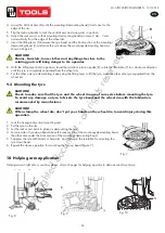
10. Helping arm application:
Helping arm at right side is auxiliary device of tyre changer for helping operator to demount and mount tyre.
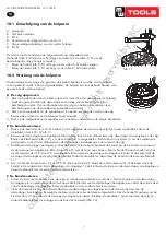
10.1 098 Help Arm Components
Each components of helping arm device are introduced as follows:
A- Swing arm B- Small helping arm
C- Roller C D- Raise-fall roller handle
F- Locking switch for right helping arm
G- Roller G
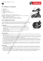
The function of helping arm control handle is as follows:
Roller lifting handle (D, Fig 8) is for lifting and lowering roller C
、
G so as to adjust
tyre demounting / mounting vertical height. Operate handle
(
D, Fig 8 ) up, then roller
C
、
G goes up
;
Operate handle
(
D, Fig 8 )down
,
then roller C
、
G goes down.
10.2 098 Help Arm Operation
It is difficult to demount and mount big and flat profile tyre. If operation is proper, it is very easy to use helping arm
device to demount and mount tyre from rim. The helping arm device may also be used
when demounting and mounting normal tyre with resistance.
a.
Clamp rim
Firstly, press both side tyre loose as per operation instruction in user’s manual. Force
of demounting and mounting is big when helping arm device is used. And rim may be
damaged easily. It is recommended that to clamp rim from outside
(
jaw protector may be
installed on jaws
)
. Tread relevant pedal to make jaws open to clamp edge of rim, move
helping arm’s rotary arm to far
-end. Put on tyre, tread relevant pedal to make jaws close
and to approach rim
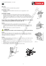
Fig 11
Fig 8
Fig 9
Fig 10
F
Fig 12
1
Fig 7
Fig. 11
.1211 . V201301
- 5
–
Lock the Hexagonal Vertical Mounting Arm, put the tyre on the rim, let
the Rocker Arm back to place as demounting the tyre. And let one side of
tyre down bead above the rear section of the Mounting/demounting head, the
other side under the front section of the Mounting/demounting head.
Suppress the trye with hands or help arm, and then spin the turntable for
mounting the tyre down bead.
Repeat the above operation for mounting the tyre up bead.
(Fig 7)
10. Helping arm application:
Helping arm at right side is auxiliary device of tyre changer for helping operator to demount and mount tyre.
10.1 098 Help Arm Components
Each components of helping arm device are introduced as follows:
A- Swing arm B- Small helping arm
C- Roller C D- Raise-fall roller handle
F- Locking switch for right helping arm
G- Roller G
The function of helping arm control handle is as follows:
Roller lifting handle (D, Fig 8) is for lifting and lowering roller C
、
G so as to adjust
tyre demounting / mounting vertical height. Operate handle
(
D, Fig 8 ) up, then roller
C
、
G goes up
;
Operate handle
(
D, Fig 8 )down
,
then roller C
、
G goes down.
10.2 098 Help Arm Operation
It is difficult to demount and mount big and flat profile tyre. If operation is proper, it is very easy to use helping arm
device to demount and mount tyre from rim. The helping arm device may also be used
when demounting and mounting normal tyre with resistance.
a.
Clamp rim
Firstly, press both side tyre loose as per operation instruction in user’s manual. Force
of demounting and mounting is big when helping arm device is used. And rim may be
damaged easily. It is recommended that to clamp rim from outside
(
jaw protector may be
installed on jaws
)
. Tread relevant pedal to make jaws open to clamp edge of rim, move
helping arm’s rotary arm to far
-end. Put on tyre, tread relevant pedal to make jaws close
and to approach rim
Fig 11
Fig 8
Fig 9
Fig 10
F
Fig 12
1
Fig 7
Fig. 12
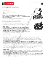
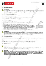
10.1 Description du bras auxiliaire
A. Bras pivotant
B. Petit bras auxiliaire
C.
Rouleau C
D. Levier pour lever/abaisser les rouleaux
F. Bouton de blocage du bras auxiliaire droit
G.
Rouleau G
La fonction du levier du bras auxiliaire fonctionne de la façon suivante :
Le levier (fig. 8, D) sert à lever et abaisser les rouleaux C, G pour régler la hauteur de
montage/démontage du pneu.
•
Montez le levier (fig. 8, D) pour faire monter les rouleaux C, G.
•
Abaissez le levier (fig. 8, D) pour faire descendre les rouleaux C, G.
10.2 Fonctionnement du bras auxiliaire
Il est difficile de démonter et monter des pneus au profil grand et plat. S’il est utilisé
correctement, le bras auxiliaire facilite sensiblement ces opérations. Le bras auxiliaire peut
aussi être utilisé pour démonter et monter des pneus normaux offrant une résistance.
A Serrer la jante
1.
Pressez légèrement les deux côté du pneu comme indiqué dans les instructions.
L’utilisation du bras auxiliaire permet une grande force lors du démontage et du
montage. La jante peut facilement être endommagée. Il est recommandé de serrer la
jante de l’extérieur (une protection peut être installée sur les mâchoires).
2.
Enfoncez la pédale pour ouvrir les mâchoires et serrer le bord de la jante, déplacez le
bras pivotant du bras auxiliaire le plus loin possible.
3. Enfoncez la pédale pour fermer les mâchoires et approcher le bord de la jante.
B Démonter le pneu
1.
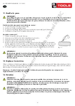
Pressez le pneu avec le rouleau C, G jusqu’à ce qu’il soit 3 cm plus bas que le bord de la jante. Lubrifiez le talon du pneu,
tournez le plateau, levez le rouleau C, G (fig. 9).
2.
Déplacez la tête de montage/démontage près du bord de la jante, en laissant un écart de 2-3 mm entre la tête de
montage/démontage et la jante. Actionnez la poignée de blocage (fig. 4, K) pour bloquer le bras vertical. Ajustez
le boulon dans la colonne pour positionner le bras pivotant, en veillant à laisser un écart de 2-3 mm entre la tête de
montage/démontage et le côté du bord de la jante.
3.
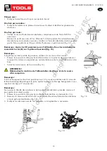
Tout près de la tête de montage/démontage, insérez le levier N dans le pneu. Utilisez le levier pour soulever le talon au-
dessus du bouton de la tête de montage/démontage. Tournez à la main le rouleau C vers l’intérieur, tirez le levier D vers le
bas et pressez la jante avec le rouleau C, en laissant un écart de 3-5 mm entre la tête de montage/démontage et la jante.
Assurez-vous que la tête de montage/démontage n’endommage pas la jante. Tournez le plateau et démontez le pneu du
talon supérieur (fig. 11).
4.
Poussez le levier D vers le haut. Levez le rouleau C, G. Pressez le bouton F. Desserrez le bras de pression droit, soulevez
le pneu, insérez le levier dans le talon inférieur près de la tête de montage/démontage. Soulevez le talon au-dessus du
bouton de la tête de montage/démontage et tournez le plateau pour démonter le talon inférieur.
C Monter le pneu
1.
Lubrifiez le bord du pneu et de la jante avec un lubrifiant pour éviter d’endommager le pneu. Ajustez la hauteur de la tête
de montage/démontage et placez le talon inférieur sur l’arrière la tête de montage/démontage et sous l’avant de la tête
de montage/démontage. Tournez le plateau pour monter le talon inférieur.
2.
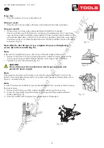
Placez le talon supérieur sur l’arrière de la tête de montage/démontage et sous l’avant de la tête de montage/démontage.
Déplacez le bras de pression et assurez-vous qu’il est bloqué. Tirez le levier D vers le bas pour presser le talon avec le
rouleau C, G sous la tête de montage/démontage. Bloquez le bloc de pression 1 sur le bord de la jante, et tournez le
plateau pour terminer le montage du pneu (fig. 12).
copyrighted
document
- all
rights
reserved
by
FBC


