


10
WSG112
ENGLISH
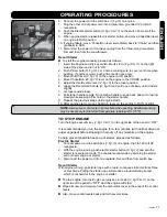
FUNCTIONAL DESCRIPTION
BEFORE STARTING
WARNING: Read, understand, and follow all instructions and warnings on the
machine and in this manual before operating.
Gas and Oil Fill-up
WARNING: Use extreme care when handing gasoline. Gasoline is extremely
flammable and the vapors are explosive. Never fuel machine indoors nor while
the engine is hot or running. Extinguish cigarettes, cigars, pipes and other
sources of ignition.
1. A plastic cup may be fitted inside the fuel fill opening to protect the tank during
manufacturing. Remove and discard it.
2. Fill tank with unleaded gasoline according to the engine manual, noting fuel
capacity: 5 L (1.3 US gal.)
3. Use the threaded gas tank cap (
F, fig.10
) to close after fill-up.
4. Fill oil reservoir according to the engine manual. 1 L of oil is adequate.
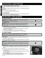
TO START ENGINE
NOTE: Engine cannot be started until the safety key is inserted into the slot
on the right side of panel of the snow thrower and turned to “on”. Remove this
ignition key to prevent unauthorized use of the equipment (see fig.11)
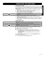
Electric Starter
Verify that your house wiring is a three-wire grounded system. Ask a licensed
electrician if you are not certain.
If your house wiring system is not a three-wire grounded system, do not use this
electric starter under any conditions.
WARNING: The electric starter is equipped with a ground three-wire power cord
and plug and is designed to operate on 120 volt AC household current. It must
be used with a properly grounded three-prong receptacle at all times to avoid the
possibility of electric shock. Follow all instructions carefully prior to operating the
electric starter.
If your home electrical system is grounded, but a three-hole receptacle is not
available, have one installed by a licensed electrician before using the electric
starter.
If you have a grounded three-prong receptacle, proceed as follows:
1. Insert and turn the Engine security key in its slot (
J, fig.10 & 11
) on the right
side of the panel.
2. Push the Primer bulb (
R, fig.10 & 12
) three (3) times, making sure to cover vent
hole when pushing.
3. Move On/Off lever (
V, fig.10
) on the engine to ON position.
4. Move Choke/Run (
W, fig.10
) lever on the engine to the CHOKE position.
5. Adjust the throttle valve lever (Z, fig.10) to the proper position.
!
!
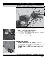
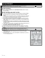
Q. CHUTE DIRECTIONAL CONTROL
The chute directional control (
Q, fig.10
) is located on the left side of the snow
thrower.
To change the direction in which snow is thrown, turn chute directional control
as follows:
Crank clockwise to discharge to the left.
Crank counterclockwise to discharge to the right.
U. SKID SHOE
The space between the shave plate and the ground can be adjusted by positioning
the skid shoes. Refer to
Skid Shoe Adjustment.
OPERATING PROCEDURES
!
Содержание WSG112
Страница 22: ...22 WSG112 ENGLISH FRANÇAIS ...
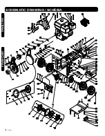
Страница 23: ...v 090220 23 FRANÇAIS ENGLISH SCHEMATIC DRAWING SCHÉMA ...
Страница 24: ...24 WSG112 ENGLISH FRANÇAIS SCHEMATIC DRAWING SCHÉMA ...
Страница 25: ...v 090220 25 FRANÇAIS ENGLISH SCHEMATIC DRAWING SCHÉMA ...
Страница 59: ...12 WSG112e ENGLISH ...
Страница 61: ...14 WSG112e ENGLISH FRANÇAIS SCHEMATIC DRAWING SCHÉMA ...
Страница 62: ...v 090220 15 FRANÇAIS ENGLISH SCHEMATIC DRAWING SCHÉMA ...