background image

Istruzioni per l’uso


modulo HF 2,4 GHz HFM4 M-LINK 

Pagina 20 

Istru

z

ioni

 per

 l’u

so 

modulo 

HF 2

,4 

GHz 

HFM4 M-L

INK 

 #

 82 5499

 (

09-

07-20

/MIWA) 

 •


Con

 ri

ser

va d

i er

rori

 e modi

fi

che! 

 • 


¤

 MU

L

T

IP

LE

X

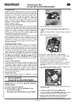
7.5.: Installare l’unità antenna 2,4 GHz 

1.  Avvitare l’antenna 2,4 GHz al supporto antenna: 

x

  Afferrare l’antenna nel punto indicato. 

x

  Avvitare saldamente, per evitare che l’antenna si allenti 

una volta installata: 

!

 Nota:

 Serrare saldamente, però senza esagerare, 

facendo attenzione ad inserire correttamente la parte 
filettata! 

2.  Raddrizzare l’unità antenna 2,4 GHz, così preparata, ed 

inserirla attentamente dalla parte inferiore del tubo di 
supporto. 

!

  Attenzione: Il perno di posizionamento, sulla parte 

superiore della radio, si deve trovare in parallelo con il 
tubo di supporto, altrimenti si corre il rischio di incastra-
re l’antenna o di danneggiare i contatti all’interno del 
tubo. 

3.  Posizionare il cavo di collegamento fra modulo HF e unità 

antenna: 

Il cavo deve essere posizionato 

sotto

al

modulo HF 2,4

GHz HFM4 M-LINK

 e 

accanto

 alla presa multifunzione 

MULTIPLEX: 

4.  Tirare verso l’alto l’unità antenna 2,4 GHz, fino a quando è 
 

visibile il giunto o fino ad una percettibile resistenza mecca

 nica: 

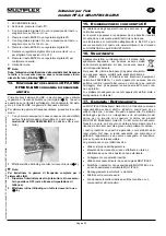
7.6.: Chiudere il coperchio posteriore 

1.  Posizionare attentamente il coperchio in posizione inclinata, 

sul bordo posteriore della radio e controllare che entrambe le 
linguette combacino con la loro sede (vedi foto seguente): 

2.  Chiudere con cautela: 


Fare attenzione che nessun cavo rimanga schiacciato. Il co-
perchio deve combaciare con la radio in modo uniforme e 
senza tensioni. 

3.  Spingere in avanti i cursori di chiusura (in direzione opposta 

a „OPEN“): 

8.

P

OSIZIONE IDEALE DELL

ANTENNA RADIO 

DURANTE IL FUNZIONAMENTO

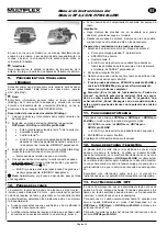
Una volta installata, l’antenna radio 2,4 GHz potrà essere 
ruotata lateralmente o inclinata verso l’alto. 

Durante il funzionamento piegare l’antenna in prossimità del 
giunto, all’incirca ad angolo retto e ruotarla infine in orizzontale, 
a destra o sinistra (vedi foto): 

Содержание 4 5611

Страница 1: ...bestra e 1 z D 75015 Bretten MULTIPLEX 2009 Printed in Germany www multiplex rc de Bedienungsanleitung 3 7 Operating Instructions 8 12 Notice d utilisation 13 17 Istruzioni per l uso 18 22 Instruccion...

Страница 2: ......
Страница 3: ...fahren Sie beim Ausbau der Baugruppe auch nach der beschriebenen Vorgehensweise x Lagern Sie die Baugruppe au erhalb des Grundger tes nur in dem leitf higen ESD Schutzbeutel niemals im direkten Kontak...

Страница 4: ...12 Kanal Betrieb Fast Response umstellbar R ckkanalf higkeit Telemetrie Das 2 4 GHz ISM Band bietet die M glichkeit Daten aus dem Modell zur ck zum Sender zu bertragen Wenn Sie einen tele metrief hige...

Страница 5: ...bels von HF Modul und Anten neneinheit im Sender Das Verbindungskabel muss sowohl unterhalb des 2 4 GHz HF Moduls HFM4 M LINK als auch neben der MULTIPLEX Multifunktionsbuchse vorbeigef hrt werden 4 2...

Страница 6: ...t und beobachtet x F hren Sie den Reichweitentest nur durch wenn keine an deren Sender in Betrieb sind Vorbereitung und Durchf hrung des Reichweitentests 1 Am Sender die Betriebsart Reichweitentest au...

Страница 7: ...eren Betrieb der Ger te erf llt Die ausf hrliche CE Konformit tserkl rung finden Sie als PDF Datei im Internet bei www multiplex rc de im Bereich DOWN LOADS unter PRODUKT INFOS 16 ENTSORGUNGSHINWEISE...

Страница 8: ...he unit from the transmitter observe the same safety precautions x If you need to store the module outside the base device always keep it in the conductive anti static bag Never allow it to make direc...

Страница 9: ...offers the possibility of transmitting data from the model back to the transmitter If you use a telemetry capable receiver the actual voltage of the receiver power supply is displayed on the transmitt...

Страница 10: ...e and the aerial unit inside the transmitter The connecting lead must pass under the HFM4 M LINK 2 4 GHz RF module and also to one side of the MULTIPLEX multi function socket 4 Pull the 2 4 GHz aerial...

Страница 11: ...ask a second person to help you with your range check so that one of you can secure and observe the model x If possible carry out the range check when no other trans mitters are operating Preparation...

Страница 12: ...nsure the safe operation of equipment The detailed CE conformity declaration can be downloaded in the form of a PDF file from the Internet under www multiplex rc de It is located in the DOWNLOADS area...

Страница 13: ...ipulations x Proc dez comme cela vous est indiqu dans les instructions pour le montage du module x Stockez les pi ces lectroniques uniquement dans leur emballage antistatique La pi ce ne doit jamais e...

Страница 14: ...sation en 16 canaux pour les metteurs du type ROYALevo ROYALpro et ROYALpro M LINK ou de 14 ms en utilisation 12 canaux Fast Response Possibilit de r ponse des canaux T l m trie La bande de fr quence...

Страница 15: ...lle ci peut tre endommag 3 Passage du c ble du module HF et de l antenne dans l metteur Le c ble de liaison doit passer sous le module HF 2 4 GHz HFM4 M LINK ainsi qu c t de la prise multifonction MUL...

Страница 16: ...uvert des anomalies lors de l utilisation Important x Effectuez le test de port e toujours avec l aide d une tierce personne qui s curise et observe le mod le x N effectuez ce test que si aucun autre...

Страница 17: ...s dez un produit qui par sa construction respecte la restriction de s curit s europ ennes en vigueurs concernant l utilisation s curis e des appareils lectroniques Vous trouverez la d claration compl...

Страница 18: ...i x Per disinstallare il modulo procedere nella stessa maniera x Se non installato conservare il modulo solo nell apposito sacchetto di protezione ESD in materiale conduttore In nessun caso usare per...

Страница 19: ...OYALpro e ROYALpro M LINK la frequen za di lavoro per i servi pu essere impostata da 21 ms modalit 16 canali di comando a 14 ms modalit 12 canali di comando Fast Response Canale di ritorno telemetria...

Страница 20: ...cavo di collegamento fra modulo HF e unit antenna Il cavo deve essere posizionato sotto al modulo HF 2 4 GHz HFM4 M LINK e accanto alla presa multifunzione MULTIPLEX 4 Tirare verso l alto l unit ante...

Страница 21: ...secon da persona che tiene e controlla il modello x Effettuare il test di ricezione solo quando non ci sono altre radio in funzione Preparativi ed esecuzione del test di ricezione 1 Sulla radio scegli...

Страница 22: ...uzione e sicurezza stabiliti dall Unione Europea La dichiarazione di conformit dettagliata CE in file PDF e pu essere scaricata dal nostro sito www multiplex rc de cliccando su DOWNLOADS e poi PRODUKT...

Страница 23: ...ura Sostenga los m dulos por el canto borde de la placa x Repita el procedimiento descrito cuando proceda a desmon tar el m dulo x Guarde el conjunto cuando lo saque de la unidad s lo en bolsas de pro...

Страница 24: ...M LINK es de 21 ms tra bajando con 16 canales y de 14 ms trabajando con 12 canales Fast Response configurables Canal de retorno Telemetr a La Banda ISM 2 4 GHz ofrece la posibilidad de enviar datos d...

Страница 25: ...n del m dulo RF y el bloque de la antena en la emisora El cable de uni n debe ser llevado por debajo del m dulo RF 2 4 GHz HFM4 M INK y tambi n junto a la clavija multifunci n MULTIPLEX 4 Extraiga el...

Страница 26: ...un comportamiento an malo del equipo de radio Importante x Haga siempre las pruebas con un ayudante que pueda observar y mantener seguro el modelo x Realice las pruebas de alcance siempre que le sea p...

Страница 27: ...ura de disposi tivos de la Uni n Europea Encontrar la declaraci n de conformidad CE completa en formato PDF en nuestra p gina web www multiplex rc de zona DOWNLOADS bajo PRODUKT INFOS 16 NOTAS SOBRE E...

Отзывы: