MULTICOM 5 PLUS INSTALLER MANUAL
6
5.
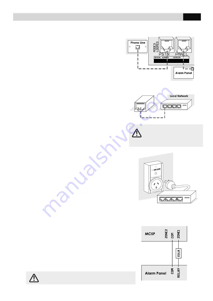
Connect the PANEL socket
directly to the
alarm panel’s dialler output using an RJ12
cable. If PSTN will be used as a
communication path, connect the PSTN
socket to a standard PSTN phone outlet.
Note: If you are NOT using PSTN, you must
disable the PSTN fault detection (option 39 =
00110000).
6.
Connect the Ethernet to the local network
, if
Ethernet will be used as a communication path,
using a patch cable. If the local network does
not use a DHCP server, you will need to
organise the static IP settings (IP address for
Multicom, Subnet Mask and Gateway). Consult
the site IT Administrator for further details.
See programming options (page 15) 55 to 59 to
enable and configure the Multicom to suit your
network.
7.
Connect the local Internet modem/router into the
provided Multicom Inteliswitch
*, if Ethernet will be
used as a communication path. This allows the
Multicom to remotely reset network devices during
prolonged network outages in an attempt to recover
network connectivity. To confirm operation press the
AUX button on the MC5P and ensure the Inteliswitch
power cycles.
The Inteliswitch will come pre-learnt to your panel but
if you have issues or want to control more Inteliswitch devices from your panel
please consult Pairing the Multicom Inteliswitch (Page 11).
8.
Interconnect Alarm Panel Relay Output
Relay/COM:
To allow immediate notification of
communication failure to the control room, program
one of the alarm panel’s relay outputs to trigger
immediately on PSTN/COMM fail. Connect the alarm
panel’s relay output to one of the Multicom’s Zone
Inputs then ensure that the zone is enabled. See
Option 30.
If the Multicom is behind a
firewall, it is important to ensure
inbound/outbound UDP ports
5000 to 5010 are open.
Note: Steps 8 & 9 are required to meet Class 4 and
up of the Australian Standard.


