12
Technical specifications
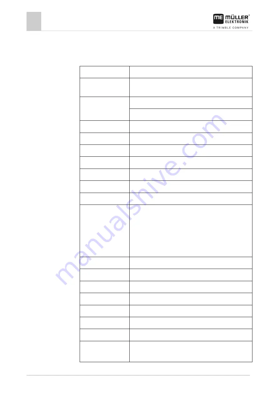
Technical specifications of the display
78
V9.20191001
31302713-02-US
Technical specifications
Technical specifications of the display
Operating voltage
10 V - 32 V
Power consumption
(operation)
0.5 A (typical) - 4 A
Power input
Typical: 6 W
Maximum: 40 W
Ambient temperature
-4°F - +140°F
Storage temperature
-22°F - +176°F
Dimensions (W x H x D)
9.6 in x 7.3 in x 2.7 in
Weight
2.43 lb
Protection class
IP6K4 according to ISO 20653:2013
EMC
ISO 14982
ESD protection
ISO 10605:2001 Level IV
Environmental testing
Vibration:
ISO 15003 Level 1 with Level 2 temperature overlap in accordance
with ISO 15003
Shock:
100 shocks per axis and direction with 0.033 g and 11 ms in
accordance with IEC 60068-2-27
Processor
i.MX 515 600MHz
Coprocessor
STM32F205
Storage
256M mDDR
Bootflash
128M SCL-NAND-Flash
Operating system
WinCE 6.0
Display
8" SVGA TFT
Housing
PC-ABS
Inputs / outputs
1 x USB
1 x Sub-D 9 socket (CAN and power supply)
12
12.1