MTU MS150112/01E Скачать руководство пользователя страница 115

7.5.4 Cylinder head cover ‒ Removal and installation

Preconditions

Engine is stopped and starting disabled.

Special tools, Material, Spare parts

Designation / Use

Part No.

Qty.

Assembly compound (Kluthe Hakuform 30-15)

X00067260

1

O-ring

(→ Spare Parts Catalog)

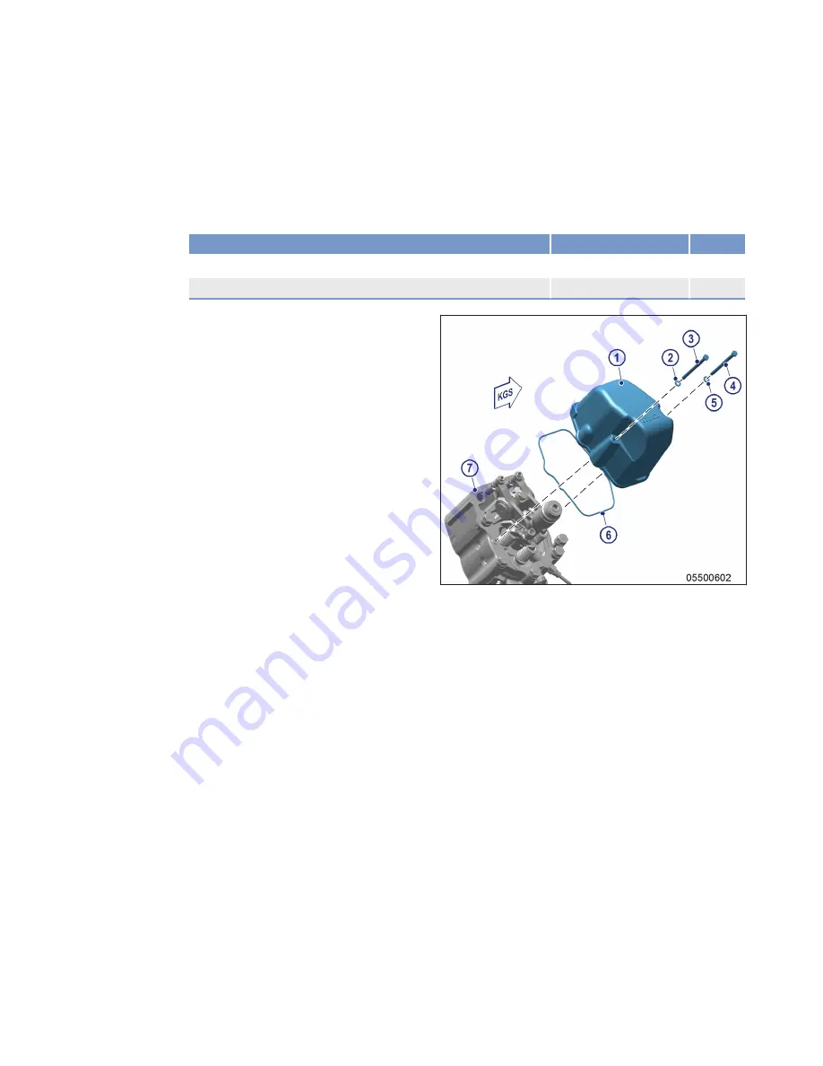
Removing cylinder head cover

1.

Clean cylinder head covers (1) if severely
soiled prior to removal.

2.

Remove screws (3, 4) with washers (2, 5).

3.

Take cylinder head cover (1) with O-ring (6)
off cylinder head (7).

Installing cylinder head cover

1.

Clean mounting surface.

2.

Check O-ring (6) for damage, replace if necessary.

3.

Coat O-ring (6) with assembly compound.

4.

Place cylinder head cover (1) with O-ring (6) on cylinder head (7).

5.

Install cylinder head cover (1) with screws (3, 4) and washers (2, 5).

MS150112/01E 2014-10

| Task Description | 115

TIM-ID: 0000026826 - 005

Содержание MS150112/01E

Страница 1: ...Operating Instructions Diesel engine 12V 4000 C64 Application group 5B MS150112 01E...

Страница 2: ...ut the prior written consent of MTU Friedrichshafen GmbH This particularly applies to its reproduction distribution editing transla tion microfilming and storage or processing in electronic systems in...

Страница 3: ...ng engine with starting system 100 7 1 3 Engine Test run 101 7 2 Auxiliary PTO 102 7 2 1 Auxiliary PTO Replacement 102 7 3 Cylinder Liner 103 7 3 1 Cylinder liner Endoscopic examination 103 7 3 2 Inst...

Страница 4: ...3 7 17 3 Charge air coolant Draining 174 7 17 4 Charge air coolant Filling 177 7 17 5 Checking charge air coolant pump pressure relief port 180 7 18 Belt Drive 181 7 18 1 Drive belt Condition check 18...

Страница 5: ...guration approved by the manufacturer in writ ing including engine management parameters In compliance with all safety regulations and in accordance with all warning notices in this manual With mainte...

Страница 6: ...rk on or around the product This personnel must be instructed repeatedly Personnel requirements All work on the product shall be carried out by trained and qualified personnel only Training at the Tra...

Страница 7: ...or must be aware of the consequences of any operations he she performs During operation the display instruments and monitoring units must be constantly observed in regard of present operating status l...

Страница 8: ...starter with compressed air Clean the interior of the flywheel housing with a class H dust extractor Observe the safety data sheet Safety requirements during maintenance and repair work Take special c...

Страница 9: ...e performing necessary welding work Hydraulic installation and removal Check function and satisfactory condition of the jigs and fixtures to be used Use only the specified jigs and fixtures for hydrau...

Страница 10: ...ent i e protect them against moisture in particular Pack age faulty electronic components or assemblies properly before dispatching for repair Moisture proof Shock proof Wrapped in antistatic foil if...

Страница 11: ...are prohibited by emission regulations Emission control units systems may only be maintained exchanged or repaired if the components used for this purpose are approved by the manu facturer Noncomplian...

Страница 12: ...be replaced Carry out leak test in accordance with the specifications Paints and varnishes Observe the relevant safety data sheet for all materials When painting in areas other than spray booths equi...

Страница 13: ...medial action NOTICE In the event of a situation involving potentially adverse effects on the product Consequences Material damage Remedial action Additional product information Safety notices 1 This...

Страница 14: ...cial packaging with aluminium foil Suspend the engine genset by the lifting eyes on the bearing pedestal or transport by means of handling equipment forklift truck capable of bearing the load Fit the...

Страница 15: ...nated in accordance with DIN ISO 1204 as viewed from driving end 4 For cylinder designation in accordance with DIN ISO 1204 the letter Ax refers to the cylinders on the left hand side of the engine 1...

Страница 16: ...pan 18 Fuel filter head 19 Supplementary fuel filter 20 Fuel filter 21 Fuel priming pump 22 Engine mounting 23 Lube oil filter 24 Vibration damper 25 Fan drive 26 Auxiliary PTO 27 Battery charging gen...

Страница 17: ...ors and injectors Overview 1 B13 Crankshaft speed 2 F70 Water level in fuel prefilter external 3 F57 Charge air coolant level 4 F33 Engine coolant level MS150112 01E 2014 10 General Information 17 TIM...

Страница 18: ...sure 6 B88 NOx 7 B16 Engine coolant pres sure 8 Y39 B1 B6 Injectors B1 B6 9 B13 Crankshaft speed 10 B10 11 Charge air pres sure B side The injectors 8 are underneath the cylinder head covers of the cy...

Страница 19: ...ntary filter 9 B34 2 Fuel pressure be fore filter 10 B34 1 Fuel pressure after filter 11 F46 Leak off fuel level 12 B5 3 Lube oil pressure before filter 13 B7 Lube oil temperature 14 B44 1 Turbocharge...

Страница 20: ...el m 100 POWER RELATED DATA power ratings are net brake power as per ISO 3046 Number of cylinders 12V Rated engine speed A rpm 1900 Net brake power w o fan fuel stop power ISO 3046 A kW 1865 GENERAL C...

Страница 21: ...R C 107 Coolant temperature after engine shutdown L C 109 Coolant antifreeze content max L 50 Coolant pump inlet pressure max L bar 2 5 Thermostat Starts to open R C 79 Thermostat Fully open R C 92 C...

Страница 22: ...ry max driving end down op tion max operating inclinations L Degrees 15 Longitudinal inclination continuous max driving end up option max operating inclinations L Degrees 15 Transverse inclination con...

Страница 23: ...unsilenced BL sound power level LW ISO 6798 R dB A 124 Engine surface noise with attenuated intake noise filter BL free field sound pressure level Lp 1m distance ISO 6798 R dB A 109 Engine surface noi...

Страница 24: ...3 2 Firing order Firing order Number of cylinders Firing order 12V A1 B5 A5 B3 A3 B6 A6 B2 A2 B4 A4 B1 24 Technical Data MS150112 01E 2014 10 TIM ID 0000026627 002...

Страница 25: ...3 3 Engine Main dimensions Engine Main dimensions Item Dimensions Length A approx 2878 mm Width B approx 1631 mm Height C approx 2393 mm MS150112 01E 2014 10 Technical Data 25 TIM ID 0000045458 001...

Страница 26: ...Page 108 Lube oil system Check engine oil level Page 154 Bar engine using starting system Page 100 Fuel prefilter Fill with fuel if fitted Coolant circuit If engine has been out of service for more t...

Страница 27: ...system Check engine oil level Page 154 Coolant circuit Check engine coolant level Page 162 Check charge air coolant level Page 172 Coolant circuit Heat coolant with coolant preheater if available see...

Страница 28: ...engine for leaks and general condition Check engine for abnormal running noises exhaust color and vibrations Air filter Check signal ring position of service indicator on air filter if fitted Battery...

Страница 29: ...g Risk of damage to hearing Wear ear protectors Preparation Item Measure Operating mode switch if applicable Switch to manual mode Coolant preheating unit if applicable Switch ON Start engine Item Mea...

Страница 30: ...fore damage to components is possible Before shutting down the engine allow it to idle until the engine temperatures decrease and constant levels are indicated Preparation Item Measure Engine Operate...

Страница 31: ...is not heated the coolant is not kept at a suitable temperature the antifreeze concentration is insufficient for the engine room tem perature the antifreeze concentration is 50 and the engine room te...

Страница 32: ...ressed air gun directly at seals or electronic components such as connectors or ECUs Plant Cleaning 1 Carry out plant cleaning only in areas where an appropriate oil separator is provided environmenta...

Страница 33: ...ctors Page 117 W1008 X Replace engine oil filter when changing engine oil or when the interval years is reached at the latest Page 158 W1009 Check layer thickness of the oil residue clean out and re p...

Страница 34: ...ks W1906 In case of valve clearance deviations check valve depth Page 109 W1907 Check and clean EGR cooler Page 142 Page 143 Table 2 Maintenance task reference table QL1 34 Maintenance MS150112 01E 20...

Страница 35: ...manually Contact Service Engine turns but does not fire Component Cause Action Engine Too cold Preheat 25 C Starter Poor rotation by starter Battery Ultra Caps low or defective Charge or replace batt...

Страница 36: ...mponent Cause Measure Air supply Air filter clogged Check Intercooler Contaminated Contact Service Exhaust turbocharger Faulty Contact Service Coolant discharge at intercooler Component Cause Measure...

Страница 37: ...digits Fault messages can also be caused by faulty sensors actuators If the fault cannot be corrected with the troubleshooting information provided in the following table contact Service Our Service...

Страница 38: ...rective action Fuel tank may be exposed to heat u Contact Service 5 HI T Charge Air ZKP Number 2 0121 931 Charge air temperature too high limit value 1 Yellow alarm warning Cause Corrective action Int...

Страница 39: ...olant circuit for charge air faulty 1 Check intercooler and coolant cooler 2 Contact Service 15 LO P Lube Oil ZKP Number 2 0100 921 Lube oil pressure too low limit value 1 Yellow alarm warning Cause C...

Страница 40: ...2 0127 931 Exhaust temperature B side too high limit value 1 Yellow alarm warning Cause Corrective action Cable damage 1 Check air filter and wiring Page 189 2 Contact Service 22 SS T Exhaust B ZKP Nu...

Страница 41: ...931 Leak off fuel level too high limit value 1 Yellow alarm warning Cause Corrective action Leak in fuel lines 1 Check fuel system 2 Contact Service 30 SS Engine Overspeed ZKP Number 2 2510 932 Engin...

Страница 42: ...filter differential pressure too high limit value 2 Red alarm engine shutdown Cause Corrective action Fuel filter not operating correctly 1 Replace fuel filter Page 123 2 Contact Service 36 HI ETC2 O...

Страница 43: ...3 Contact Service 52 SS T Lube Oil ZKP Number 2 0125 932 Lube oil temperature too high limit value 2 Red alarm engine shutdown Cause Corrective action Insufficient oil 1 Check engine oil level Page 1...

Страница 44: ...ge leaks low coolant level 1 Activate fan emergency operating mode if required 2 Allow engine to cool down 3 Check engine coolant cooler clean if dirty 4 Acknowledge alarm 5 Restart engine Page 29 6 C...

Страница 45: ...heck fuel lines for leakage 2 Check fuel filter low pressure side 3 Replace fuel filter Page 123 4 Contact Service 67 HI T Coolant ZKP Number 2 0120 931 Coolant temperature too high limit value 1 Yell...

Страница 46: ...readjusted towards late Cause Corrective action HP fuel block jamming or HP fuel control block wiring faulty 1 Check wiring Page 189 2 Contact Service 83 LO P Fuel Common Rail ZKP Number 2 0104 921 R...

Страница 47: ...e Corrective action Starter rotates too slowly or does not rotate at all 1 Observe additional messages 2 Contact Service 93 SS T Preheat ZKP Number 2 1090 922 Preheating temperature too low limit valu...

Страница 48: ...nitoring system Yellow alarm warning Cause Corrective action Hour meter faulty u Contact Service 118 LO ECU Supply Voltage ZKP Number 2 0140 921 Supply voltage too low limit value 1 Yellow alarm warni...

Страница 49: ...too high limit value 1 Yellow alarm warning Cause Corrective action Electronics overheated 1 Reduce power 2 Improve engine room ventilation 180 AL CAN1 Node Lost ZKP Number 2 0500 680 Connection to a...

Страница 50: ...Check devices connected to CAN 2 Contact Service 184 AL CAN PU Data Flash Error ZKP Number 2 0500 684 CAN PU data flash fault Cause Corrective action A programming error occurred when attempting to co...

Страница 51: ...s required 2 Check shielding improve shielding if necessary 3 Contact Service 189 AL CAN2 Error Passive ZKP Number 2 0500 689 CAN controller 2 error Yellow alarm warning Cause Corrective action Missin...

Страница 52: ...rectified when engine is restarted Page 29 3 Contact Service 204 SD Level Lube Oil ZKP Number 1 8004 602 Lube oil level sensor signal error Yellow alarm warning Cause Corrective action Lube oil level...

Страница 53: ...as necessary Page 189 2 Fault is rectified when engine is restarted Page 29 3 Contact Service 208 SD P Charge Air ZKP Number 1 8004 566 Charge air pressure sensor signal error Yellow alarm warning Ca...

Страница 54: ...is rectified when engine is restarted Page 29 3 Contact Service 214 SD P Crankcase ZKP Number 1 8004 568 Crankcase pressure sensor signal error Yellow alarm warning Cause Corrective action Crankcase...

Страница 55: ...rectified when engine is restarted Page 29 3 Contact Service 220 SD Level Coolant Water ZKP Number 1 8004 584 Coolant level sensor signal error Yellow alarm warning Cause Corrective action Coolant lev...

Страница 56: ...lt is rectified when engine is restarted Page 29 3 Contact Service 227 SD Oil Pressure before Filter ZKP Number 1 8004 620 Lube oil pressure sensor before filter signal error Yellow alarm warning Caus...

Страница 57: ...sary Page 189 2 Fault is rectified when engine is restarted Page 29 3 Contact Service 231 SD Camshaft Speed ZKP Number 1 8004 499 Camshaft sensor signal error Yellow alarm warning Cause Corrective act...

Страница 58: ...filter Yellow alarm warning Cause Corrective action Fuel differential pressure sensor faulty u Observe additional messages 240 SD P Fuel ZKP Number 1 8004 565 Fuel sensor signal error Yellow alarm war...

Страница 59: ...ssary Page 189 2 Fault is rectified when engine is restarted Page 29 3 Contact Service 269 SD Loadp Analog Filt ZKP Number 2 8006 588 Load pulse analog signal faulty Yellow alarm warning Cause Correct...

Страница 60: ...1 8004 522 Wiring faulty cylinder A3 Yellow alarm misfiring Cause Corrective action Short circuit fault in injector wiring cylinder A3 1 Check solenoid valve 2 Contact Service 324 AL Wiring Cylinder A...

Страница 61: ...8004 527 Wiring faulty cylinder A8 Yellow alarm misfiring Cause Corrective action Short circuit fault in injector wiring cylinder A8 1 Check solenoid valve 2 Contact Service 329 AL Wiring Cylinder A9...

Страница 62: ...1 8004 532 Wiring faulty cylinder B3 Yellow alarm misfiring Cause Corrective action Short circuit fault in injector wiring cylinder B3 1 Check solenoid valve 2 Contact Service 334 AL Wiring Cylinder B...

Страница 63: ...8004 537 Wiring faulty cylinder B8 Yellow alarm misfiring Cause Corrective action Short circuit fault in injector wiring cylinder B8 1 Check solenoid valve 2 Contact Service 339 AL Wiring Cylinder B9...

Страница 64: ...Injector wiring fault cylinder A3 Yellow alarm misfiring Cause Corrective action Disruption fault in injector wiring cylinder A3 1 Check injector wiring and solenoid valve 2 Contact Service 344 AL Ope...

Страница 65: ...jector wiring fault cylinder A8 Yellow alarm misfiring Cause Corrective action Disruption fault in injector wiring cylinder A8 1 Check injector wiring and solenoid valve 2 Contact Service 349 AL Open...

Страница 66: ...Injector wiring fault cylinder B3 Yellow alarm misfiring Cause Corrective action Disruption fault in injector wiring cylinder B3 1 Check injector wiring and solenoid valve 2 Contact Service 354 AL Ope...

Страница 67: ...jector wiring fault cylinder B8 Yellow alarm misfiring Cause Corrective action Disruption fault in injector wiring cylinder B8 1 Check injector wiring and solenoid valve 2 Contact Service 359 AL Open...

Страница 68: ...shutdown possible Cause Corrective action Electronics possibly faulty 1 Start ITS 2 Replace engine governor if required 3 Check additional messages if ITS indicates diagnosis Electronics OK e g wiring...

Страница 69: ...al input 1 Yellow alarm warning Cause Corrective action Short circuit or wire break on transistor output 1 plant side TOP 1 u Check wiring to plant 382 AL Wiring TOP 2 ZKP Number 2 8006 639 Line disru...

Страница 70: ...maximum continuous rate was exceeded u If the alarm remains contact Service 400 AL Open Load Digital Input 1 ZKP Number 2 8006 625 Line disruption on digital input 1 Yellow alarm warning Cause Correc...

Страница 71: ...Check wiring Page 189 2 Check target device input 3 Contact Service 404 AL Open Load Digital Input 5 ZKP Number 2 8006 629 Line disruption on digital input 5 Yellow alarm warning Cause Corrective act...

Страница 72: ...over switch 1 Check wiring Page 189 2 Check target device input 3 Contact Service 408 AL Open Load Emerg Stop Input ESI ZKP Number 2 8006 633 Open circuit at input for emergency stop Yellow alarm warn...

Страница 73: ...Check wiring Page 189 2 Check supply 3 Contact Service 413 HIHI U PDU ZKP Number 2 0141 932 Injector voltage too high limit value 2 Red alarm engine shutdown Cause Corrective action Cable damage or f...

Страница 74: ...ing Cause Corrective action Water level sensor of fuel prefilter is faulty Short circuit or wire break 1 Check sensor and wiring replace as necessary Page 189 2 Contact Service 438 LO P Fuel 2 Common...

Страница 75: ...580 Ambient air pressure sensor signal error Yellow alarm warning Cause Corrective action Ambient air pressure sensor faulty u Replace engine governor 446 SD P HD2 ZKP Number 1 8004 599 Rail pressure...

Страница 76: ...ion Active ZKP Number 2 7000 011 Power reduction has been activated Red alarm power reduction has been activated Cause Corrective action Engine operation outside standard limit values This message can...

Страница 77: ...yellow alarm from the system Yellow alarm warning Cause Corrective action Various causes possible u Observe additional messages 479 AL Comb Alarm Red Plant ZKP Number 2 8006 002 Combined red alarm fr...

Страница 78: ...of the 3rd secondary turbocharger too high limit value 1 Yellow alarm warning Cause Corrective action Obstructed charge air circuit or fault in turbocharger u Reduce power 491 SS ETC4 Overspeed ZKP N...

Страница 79: ...Battery Not Charging ZKP Number 1 4500 903 No battery charge Yellow alarm warning Cause Corrective action Battery is not charged by battery charging generator u Check battery charging generator and w...

Страница 80: ...g Cause Corrective action Override suppresses other alarms u Deactivate override button again 515 AL Starter Not Engaged ZKP Number 2 1090 926 Yellow alarm start termination possible Cause Corrective...

Страница 81: ...running This may lead to overpressure in the HP system which can damage the engine u Instruct operators to switch off the power supply only after the engine has come to a standstill 558 AL Wiring PWM...

Страница 82: ...lf actuator sensor and replace if necessary Page 189 2 Contact Service 582 AL Emergency Stop Failed ZKP Number 1 1005 006 Emergency stop command from locomotive control system was not executed Flashin...

Страница 83: ...ensor and wiring replace as necessary Page 189 2 Contact Service 593 AL T Lube Oil Pan Low ZKP Number 2 1090 929 Lube oil temperature in oil pan too low Cause Corrective action Preheating time not lon...

Страница 84: ...pressure relief valve second rail Cause Corrective action HP fuel block jamming or HP fuel control block wiring faulty 1 Check wiring and HP fuel control block Page 189 2 Contact Service 599 AL L2 PR...

Страница 85: ...AN request 606 AL Double Nodes Lost CAN 1 2 ZKP Number 2 0500 691 ECU does not detect monitored CAN bus device Red alarm forced idle Cause Corrective action A node has failed on both CANs Short circui...

Страница 86: ...rt circuit on PWM channel HP fuel control block 1 Check wiring Page 189 2 Contact Service 611 AL Wiring HP Fuel Control Block 2 ZKP Number 1 1302 902 Wiring faulty at HP fuel control block 2 Yellow al...

Страница 87: ...pressure too high Yellow alarm warning Cause Corrective action Fuel prefilter not operating correctly 1 Replace fuel prefilter 2 Contact Service 615 AL EIL Protection ZKP Number 2 0610 951 Alarm for P...

Страница 88: ...cted device or check connected device itself actuator sensor and replace if necessary Page 189 2 Contact Service 627 AL Wiring PWM_CM9 ZKP Number 1 1041 929 Wiring problem at PWM_CM9 channel Yellow al...

Страница 89: ...ecirculation shutoff flap B or flap mechanical system is defective 1 Replace actuator or flap 2 Contact Service 631 AL Bypass Flap Defect ZKP Number 1 0700 051 Bypass flap is faulty Yellow alarm warni...

Страница 90: ...091 Moisture sensor signal error TRICAN HDT2800 Yellow alarm warning Cause Corrective action Moisture sensor TRICAN HDT2800 defective 1 Check sensor and wiring replace as necessary Page 189 2 Contact...

Страница 91: ...or wire break 1 Check sensor and wiring B34 3 replace as necessary Page 189 2 Fault is rectified when engine is restarted Page 29 3 Contact Service 644 AL L1 P Fuel b o F ZKP Number 2 0164 921 Fuel s...

Страница 92: ...ak 1 Check sensor and wiring B10 11 replace as necessary Page 189 2 Fault is rectified when engine is restarted Page 29 662 SD Smart NOx Heating Element ZKP Number 1 0700 141 Smart NOx sensor heating...

Страница 93: ...ontact Service 723 SD T Exhaust before DOC A ZKP Number 1 0200 921 Exhaust temperature sensor before DOC A signal error Yellow alarm warning Cause Corrective action T exhaust sensor before DOC A fault...

Страница 94: ...aulty Short circuit or wire break 1 Check sensor and wiring replace as necessary Page 189 2 Contact Service 727 AL L1 Delta T LT Intercooler ZKP Number 2 1075 901 T max coolant intercooler has exceede...

Страница 95: ...in turbocharger 1 Reduce power 2 Check air filter 3 Contact Service 731 AL L1 T Exhaust Before DPF ZKP Number 2 0201 921 L1 T exhaust before DPF violated Yellow alarm warning Cause Corrective action...

Страница 96: ...mber 2 0203 921 L1 P DPF differential pressure violated Yellow alarm warning Cause Corrective action Excessive pressure loss in DPF due to contamination 1 Check DPF 2 Contact Service 736 AL L2 T DPF D...

Страница 97: ...Pressure Standard ZKP Number 2 1602 924 L4 P DPF differential pressure standard violated Red alarm Cause Corrective action Excessive pressure loss in DPF due to contamination 1 Check DPF 2 Contact Ser...

Страница 98: ...ctional error in the flash memory 1 Replace flash memory 2 Contact Service 745 AL Emission Fault 1 ZKP Number 2 1600 004 Emission fault 1 Yellow alarm warning Cause Corrective action NOx tricane or ex...

Страница 99: ...nger zone Barring engine manually lateral installation 1 Remove cover from flywheel housing 2 Engage barring device 2 in ring gear and install on flywheel housing Use barring device F6787910 3 Set rat...

Страница 100: ...om the engine Barring engine with starting sys tem 1 Release latch 1 of connector X3 2 Note Seal unused connectors with the supplied protective cap 2 Remove connector from engine governor 3 Turn engin...

Страница 101: ...no persons in the en gine s danger zone WARNING High level of engine noise when the engine is running Risk of damage to hearing Wear ear protectors Engine Test run 1 Start engine Page 29 2 Perform tes...

Страница 102: ...components Damage to component Observe manufacturer s instructions Check components for special cleanliness Replacing auxiliary PTO 1 Remove auxiliary PTO 3 by releasing the screws 1 on the gearcase...

Страница 103: ...top piston ring and bottom edge of carbon scraper ring First signs of marks left by top piston ring Bright mark on entire circumference Faultless even honing pattern First signs of marks left by lowe...

Страница 104: ...ending on findings Do not take any action or carry out a further endoscopic examination as part of maintenance work or contact Service cylinder liner must be replaced Final steps 1 Install injector Pa...

Страница 105: ...nd the liner It appears rather darker within the honed struc ture in contrast to the bright metallic running surface The honing pattern is undis turbed Discolorations extend in stroke direction and ma...

Страница 106: ...tion are similar A thorough investigation and compliance with the above evaluation criteria allow an unambiguous evaluation To avoid unnecessary disassembly work it is recommended that another inspect...

Страница 107: ...ING Hot oil Oil can contain combustion residues which are harmful to health Risk of injury and poisoning Wear protective clothing gloves and goggles safety mask Avoid contact with skin Do not inhale o...

Страница 108: ...re parts Designation Use Part No Qty Engine oil Valve gear Lubrication 1 Remove cylinder head covers Page 115 2 Fill oil chambers of valve bridges with oil 3 Fill oil chambers of rocker arms and adjus...

Страница 109: ...y Depth gauge 200 mm Y20000918 1 Preparatory steps 1 Remove cylinder head covers Page 115 2 Remove injector Page 118 3 Remove sleeves arrow 4 Install barring device Page 99 5 Rotate crankshaft with ba...

Страница 110: ...ing screw 1 and remove valve bridge Do not remove rocker arm 2 4 Measure distance between valve stem end and cylinder head top at the spark plug bore with depth gauge see figure The specified value fo...

Страница 111: ...3 Install sleeves arrow 4 Install injector Page 118 5 Install cylinder head cover Page 115 MS150112 01E 2014 10 Task Description 111 TIM ID 0000045593 001...

Страница 112: ...key F30002815 1 Torque wrench 60 320 Nm F30452768 1 Socket wrench 24 mm F30039526 1 Engine oil Preparatory steps 1 Remove cylinder head cover Page 115 2 Install barring device Page 99 Note The OT mark...

Страница 113: ...e to determine the distance between valve bridge and rocker arm 5 If the deviation from the set value exceeds 0 1 mm adjust valve clearance Adjusting valve clearance 1 Release locknut 1 2 Insert feele...

Страница 114: ...Final steps 1 Remove barring device Page 99 2 Install cylinder head cover Page 115 3 Enable engine start 114 Task Description MS150112 01E 2014 10 TIM ID 0000026629 003...

Страница 115: ...der head covers 1 if severely soiled prior to removal 2 Remove screws 3 4 with washers 2 5 3 Take cylinder head cover 1 with O ring 6 off cylinder head 7 Installing cylinder head cover 1 Clean mountin...

Страница 116: ...from the engine s danger zone WARNING High level of engine noise when the engine is running Risk of damage to hearing Wear ear protectors HP pump Relief bore check 1 Visually inspect relief bore 1 for...

Страница 117: ...or Replacement Special tools Material Spare parts Designation Use Part No Qty Injector Spare Parts Catalog Replacing injector u Remove injector and install new injector Page 118 MS150112 01E 2014 10 T...

Страница 118: ...rench 60 320 Nm F30452768 1 Assembly paste Optimoly Paste White T 40477 1 Grease Kluthe Hakuform 30 10 emulsifier X00029933 1 Engine oil O ring Spare Parts Catalog WARNING Fuels are combustible Risk o...

Страница 119: ...inder head 9 Remove O rings 3 and damper ring 4 from injector 10 Clean all mating and sealing surfaces 11 If carbon residue is present Clean sealing face on cylinder head and protective sleeve with mi...

Страница 120: ...Screw M12 Preload torque Engine oil 5 Nm to 10 Nm Note Ensure special cleanness 11 Coat thread and sealing cone of adapter 1 with engine oil 12 Install adapter 1 and use torque wrench to tighten to th...

Страница 121: ...on nut thrust screw Tightening torque Engine oil 40 Nm 5 Nm 17 Fit cable connector onto injector Note The CDC parameters must be reset other wise the emission certification of the en gine is no longer...

Страница 122: ...Risk of severe component damage and other severe damage Avoid naked flames electrical sparks and ignition sources Do not smoke Venting LP fuel system 1 Open threaded vent plug 1 and connect a suitable...

Страница 123: ...TICE Fuels are flammable and explosive Risk of severe component damage and other severe damage Avoid naked flames electrical sparks and ignition sources Do not smoke Fuel filter Replacement 1 Provide...

Страница 124: ...es electrical sparks and ignition sources Do not smoke Supplementary fuel filter Re placement 1 Remove easy change filter 2 with filter wrench 2 Clean sealing surface on filter head 1 3 Coat seal on e...

Страница 125: ...aterial Spare parts Designation Use Part No Qty Turbine housing Spare Parts Catalog Exhaust turbocharger low pressure charger u Check turbine housing Page 126 Exhaust turbocharger high pressure u Chec...

Страница 126: ...re Parts Catalog WARNING Component is hot Risk of burning Wear protective gloves WARNING Coolant is hot and under pressure Risk of injury and scalding Let the engine cool down Wear protective clothing...

Страница 127: ...rger LP left side 1 Loosen screws on holders 2 3 2 Remove holders 2 3 with coolant vent lines 1 4 from heat shield 3 Remove temperature sensor 1 lambda sensor 2 and test lead for sensor B91 3 3 from e...

Страница 128: ...of the turbine housing of the HP exhaust turbocharger re quires special steps Page 134 Removing heat shield 1 Remove screws 1 and take off with hold er 2 and washers 2 Remove screws 3 and take off wit...

Страница 129: ...housing Checking turbine housing Note Cracks are only permissible in the direction of circumference of the spiral u Check turbine housing endoscopically for cracks from the inside Result If the crack...

Страница 130: ...nsole and tighten to specified tightening torque Name Size Type Lubricant Value Standard Screws Tightening torque Assembly paste Ul tra Therm MTU 42 Nm 4 Nm Installing heat shield 1 Install heat shiel...

Страница 131: ...socket for NOx sensor to tighten to specified tightening torque Name Size Type Lubricant Value Standard Sensor M20 x 1 5 Tightening torque 50 Nm 10 Nm 2 Install pipe half clamps 2 3 and coolant vent l...

Страница 132: ...ded adapter 1 of temperature sensor B4 on exhaust elbow and use torque wrench to tight en nut 2 to specified tightening torque Name Size Type Lubricant Value Standard Threaded adapter M14 x 1 5 Tighte...

Страница 133: ...lines 1 4 and hold er 2 8 on heat shield and tighten screws Final steps general 1 Fill with engine coolant Page 167 2 Fill charge air coolant circuit Page 177 MS150112 01E 2014 10 Task Description 133...

Страница 134: ...oil Assembly paste Ultra Therm MTU 50547 1 O ring Spare Parts Catalog WARNING Component is hot Risk of burning Wear protective gloves WARNING Coolant is hot and under pressure Risk of injury and scal...

Страница 135: ...g LP requires special steps Page 126 Removing heat shield 1 Remove screws 1 and take off with hold er 2 and washers 2 Remove screws 2 and take off with heat shield 1 and washers Removing exhaust Y pip...

Страница 136: ...move insulation 2 Checking turbine housing Note Cracks are only permissible in the direction of circumference of the spiral u Check turbine housing endoscopically from the inside for cracks Result If...

Страница 137: ...2 with torque wrench to specified tightening torque Name Size Type Lubricant Value Standard Nut Tightening torque Assembly paste Ul tra Therm MTU 27 Nm 2 Nm Installing exhaust Y pipe insula tion u Ins...

Страница 138: ...d screws 2 and tighten to specified tightening torque Name Size Type Lubricant Value Standard Screws Tightening torque Engine oil 42 Nm 4 Nm 2 Install holder 2 with washers and screws 1 and tighten 13...

Страница 139: ...nstall coolant vent lines 2 4 and hold ers 1 3 on heat shield and tighten screws 2 Fill with engine coolant Page 167 3 Fill charge air coolant Page 177 MS150112 01E 2014 10 Task Description 139 TIM ID...

Страница 140: ...d Risk of chemical burns Wear protective goggles Wear protective gloves Intercooler Leak check 1 With the engine at standstill open the plug screws in the charge air elbows on the left and right engin...

Страница 141: ...n 2 Screw 3 Washer 4 Coolant line 5 Exhaust gas recirculation after EGR cooler 6 Washer 7 Screw 8 Intercooler 9 EGR cooler 10 Exhaust gas recirculation previous to EGR cooler with EGR shut off flap 11...

Страница 142: ...hearing risk of rupturing internal organs Never direct air jet at people Always wear safety goggles face mask and ear defenders NOTICE Contamination of components Damage to component Observe manufact...

Страница 143: ...ct air jet at people Always wear safety goggles face mask and ear defenders Checking EGR cooler Item Findings Action Visually inspect all components for damage Damaged Recondition Replace Check all se...

Страница 144: ...7 12 4 Exhaust flaps Overview 1 EGR shutoff flap 2 Donor cylinder flap 1 Bypass flap 144 Task Description MS150112 01E 2014 10 TIM ID 0000027110 005...

Страница 145: ...st flaps and control linkage by mov ing the assembly at the points arrows and make sure that there is no excessive play Result If exhaust flap is jamming sluggish or has too much play contact Service...

Страница 146: ...7 12 6 Exhaust flaps Overview 1 EGR shutoff flap 2 Donor cylinder flap 1 Bypass flap 146 Task Description MS150112 01E 2014 10 TIM ID 0000044519 001...

Страница 147: ...t flaps 2 Check operability and ease of movement of coupling rod 1 by moving it at the speci fied points arrows and make sure that there is no excessive play Result Replace coupling rod 1 if it is jam...

Страница 148: ...rod 1 by moving it at the speci fied points arrows and make sure that there is no excessive play Result Replace coupling rod 1 if it is jamming sluggish or features excessive play Page 149 148 Task De...

Страница 149: ...RNING Exhaust flaps air flaps close rapidly Risk of crushing Using a suitable tool check exhaust flaps air flaps by pressing the actuating linkage to its limit several times and releasing it WARNING C...

Страница 150: ...rod donor cylinder flap Note For installation position of exhaust flaps refer to overview Page 144 1 Remove guard plates of exhaust flap 2 Remove locknuts 4 3 Remove washers 3 4 Remove locking screw...

Страница 151: ...owing each change to the mechanism of the exhaust recirculation system an actuator test teach in routine with DiaSys must be carried out Page 191 MS150112 01E 2014 10 Task Description 151 TIM ID 00000...

Страница 152: ...eck Preconditions Engine is stopped and starting disabled Checking starter condition 1 Check securing screws of starter for secure seating and tighten if required 2 Check wiring Page 189 152 Task Desc...

Страница 153: ...e is stopped and starting disabled Engine oil level check at sight glass 1 Make a preliminary visual check of oil lev el 2 at the sight glass 1 2 A proper engine oil level check must al ways be carrie...

Страница 154: ...ith the engine running 1 After the engine has run for approx 10 minutes at a constant speed of 600 to 900 rpm pull out oil dipstick from guide tube and wipe it 2 Insert dipstick into guide tube up to...

Страница 155: ...of burns Risk of poisoning Wear protective clothing protective gloves and safety glasses facial protection Avoid contact with skin Do not inhale oil vapor Oil change without semirotary hand pump Drai...

Страница 156: ...icant Value Standard Screw M18 x 1 5 Tightening torque Engine oil 50 Nm 10 Nm 6 Screw in drain plugs 2 4 and tighten with torque wrench to the specified torque Name Size Type Lubricant Value Standard...

Страница 157: ...ear protective clothing gloves and goggles safety mask Avoid contact with skin Do not inhale oil vapor WARNING High level of engine noise when the engine is running Risk of damage to hearing Wear ear...

Страница 158: ...g Wear protective clothing gloves and goggles safety mask Avoid contact with skin Do not inhale oil vapor Engine oil filter Replacement 1 Stop engine and disable engine start 2 After warning up and di...

Страница 159: ...safety valve 7 Check condition of the new oil filter sealing ring and coat it with engine oil 8 Screw the engine oil filter on and tighten by hand 9 Replace other engine oil filters in the same way 1...

Страница 160: ...orm 30 10 emulsifier X00029933 1 Filter sleeve 8591840001 1 Set of seals 23540304 1 WARNING Hot oil Oil can contain combustion residues which are harmful to health Risk of injury and poisoning Wear pr...

Страница 161: ...standpipe 11 onto rotor lower sec tion 9 13 Insert the new filter sleeve with stiffener plate in rotor cap 12 with the smooth sur face facing the rotor cap 14 Check sealing ring 10 fit new one if nec...

Страница 162: ...pe 2 Continue to turn cap counterclockwise and remove 3 Check engine coolant level engine coolant must be visible at bottom edge of cast in eye of filler neck Checking engine coolant level at remote c...

Страница 163: ...e Special tools Material Spare parts Designation Use Part No Qty Coolant Engine coolant change 1 Drain engine coolant Page 164 2 Fill with engine coolant Page 167 MS150112 01E 2014 10 Task Description...

Страница 164: ...Turn cover on coolant expansion tank counterclockwise until the first stop and allow pressure to es cape 3 Continue to turn cover counterclockwise and remove 4 Extract remaining engine coolant in the...

Страница 165: ...n remaining engine coolant at EGR cooler A and B side arrow Final steps 1 Close all open drain points 2 Fit cover on filler neck and close it MS150112 01E 2014 10 Task Description 165 TIM ID 000003076...

Страница 166: ...ain the respective coolant circuit Donor cylinder flap Drain engine coolant Page 164 Bypass flap EGR shutoff flap Drain charge air coolant Page 174 Note The procedure is described for one exhaust flap...

Страница 167: ...ngine to cool down Wear protective clothing protective gloves and safety glasses facial protection NOTICE Filling cold coolant into a hot engine can result in thermal stress Danger of crack formation...

Страница 168: ...rain valve 6 Check proper condition of cap and clean sealing faces if required 7 Fit cap on filler neck and close it 8 Start engine Page 29 and shut down af ter 10 seconds of operation without load Pa...

Страница 169: ...Fit cap on filler neck and turn until the first stop to close 5 Start engine Page 29 and shut down af ter 10 seconds of operation without load Page 30 6 Turn cap counterclockwise and remove 7 Check e...

Страница 170: ...ng damage Wear ear protection Engine coolant pump Relief bore check 1 Check relief bore arrow for oil and coolant discharge 2 Stop engine Page 30 and disable en gine start observe general safety instr...

Страница 171: ...cool down Wear protective clothing protective gloves and safety glasses facial protection WARNING Loud engine noises with the engine running Risk of hearing damage Wear ear protection Engine coolant...

Страница 172: ...st stop and allow pressure to escape 2 Continue to turn cap counterclockwise and remove Note Charge air coolant must be visible at mark er plate 3 Check charge air coolant level 4 Top up charge air co...

Страница 173: ...ecial tools Material Spare parts Designation Use Part No Qty Coolant Charge air coolant Change 1 Drain charge air coolant Page 174 2 Fill with charge air coolant Page 177 MS150112 01E 2014 10 Task Des...

Страница 174: ...Wear protective clothing protective gloves and safety glasses facial protection Charge air coolant Draining 1 Provide a suitable container in which to collect the charge air coolant 2 Turn cover on c...

Страница 175: ...oler high pressure arrow 8 Drain remaining charge air coolant at inter cooler low pressure A side arrows 9 Drain remaining charge air coolant at inter cooler low pressure B side arrow MS150112 01E 201...

Страница 176: ...fully pull the coolant line 3 out of the union 12 Loosen the union nut 1 of the upper cool ant line 2 13 Pull the coolant line 2 somewhat out of the union Note Wait until no more coolant comes out of...

Страница 177: ...ow engine to cool down Wear protective clothing protective gloves and safety glasses facial protection NOTICE Filling cold coolant into a hot engine can result in thermal stress Danger of crack format...

Страница 178: ...t stop to close 5 Start engine Page 29 6 After 10 seconds of running the engine without load shut down the engine Page 30 7 Turn cap counterclockwise and remove 8 Check charge air coolant level Page 1...

Страница 179: ...p on coolant expansion tank coun terclockwise until the first stop and allow pressure to escape 11 Continue to turn cap counterclockwise and remove 12 Check charge air coolant level Page 172 and top u...

Страница 180: ...protectors Checking charge air coolant pump pressure relief port 1 Check pressure relief port arrow for oil and coolant discharge Note Observe safety regulations when carrying out maintenance and rep...

Страница 181: ...ed Guard is removed Drive belt Condition check Item Findings Action Drive belt A Singular cracks None Drive belt B Cracks on entire circumference Replace Page 184 Drive belt C Chunking Drive belt Belt...

Страница 182: ...ask and ear protectors Checking battery charging generator Item Findings Action Ventilation area arrow Clean None Ventilation area arrows Contaminated Clean Cleaning battery charging generator Note Dr...

Страница 183: ...pecified tool and equipment Adjusting belt tension 1 Remove protective cover 2 Slacken screws 1 and 2 by half a turn Result Belt tensioner moves against the drive belt and tensions it 3 Tighten screw...

Страница 184: ...pter or box wrench on screw 1 and press belt tensioner in the di rection indicated by the arrow as far as it will go 4 Tighten screw 3 5 Remove the used drive belt 6 Fit new drive belt 7 Slacken screw...

Страница 185: ...r 2 Check belt condition visually Page 181 Result For drive belt replacement Page 187 Checking V belt tension 1 Switch on belt tension tester 2 Hold measuring tip of belt tension tester over belt driv...

Страница 186: ...ved 2 Tighten stud 1 until the required frequen cy is achieved 3 Tighten all screws 2 with torque wrench to specified tightening torque Name Size Type Lubricant Value Standard Screw Tightening torque...

Страница 187: ...elt Spare Parts Catalog Preparatory steps 1 Remove protective cover 2 Remove fan Replacing drive belt 1 Release screws 2 2 Slacken off stud 1 until drive belt can be removed 3 Clean belt pulleys 4 Fit...

Страница 188: ...dition Item Findings Action Visually inspect mounts Damage Brittleness Deformation Crack formation Swelling visible Replace Contact Service Check securing screws for firm seating 1 Check securing scre...

Страница 189: ...ips are closed and intact 4 Replace faulty cable clips 5 Check that cable clamps are firm tighten loose cable clamps 6 Replace faulty cable clamps 7 Visually inspect the following electrical line comp...

Страница 190: ...set the emission certification becomes invalid Resetting parameters for drift correction CDC with DiaSys 1 Use DiaSys to reset the CDC parameters Dialog system DiaSys E531920 2 If no DiaSys is availab...

Страница 191: ...air flaps by pressing the actuating linkage to its limit several times and releasing it WARNING Component is hot Risk of burns Wear protective goggles Checking actuators visually Item Findings Action...

Страница 192: ...rect ly Actuator general condition Heavily contaminated by black ex haust Replace Checking actuators with DiaSys Note For installation position of exhaust flaps refer to overview Page 144 1 Switch on...

Страница 193: ...face using a cloth moistened with isopropyl alcohol 2 Remove dirt from the connector and cable surfaces with isopropyl alcohol 3 Check legibility of cable labels Clean or replace illegible labels Clea...

Страница 194: ...table test probe e g test prod The contacts in the plug connection can be bent Carry out check of plug connection only with test connectors Checking plug connections at engine governor 1 Check all plu...

Страница 195: ...r protective gloves NOTICE High voltage Risk of damage to components Switch off ignition before replacing components NOTICE Ceramic cell breakage due to shock or impact Risk of damage to components Av...

Страница 196: ...nly just before installation Note Do not wipe off the thread lubricant applied by the manufacturer 3 Coat sensor thread with specified assembly compound as required 4 Screw in sensor by hand 5 Tighten...

Страница 197: ...ot Risk of burning Wear protective gloves NOTICE Ceramic cell breakage due to shock or impact Risk of damage to components Avoid shocks and impacts Exercise extreme care when handling sensors NOTICE H...

Страница 198: ...off the thread lubricant applied by the manufacturer 2 Coat sensor thread with specified assembly compound as required 3 Screw in sensor by hand 4 Tighten nut 2 to specified torque using a torque wre...

Страница 199: ...as soon as possible 2nd function Read out fault codes CCT Circuit CLS Coolant Level Sensor Monitors coolant level CM Current Measurement Current measured value CPS Coolant Pressure Sensor Monitors coo...

Страница 200: ...exceeds 1st maximum limit HIHI High High Alarm Measured value exceeds 2nd maximum limit HP High Pressure HT High Temperature IDM Interface Data Module Memory module for interface data IIG Initiale Inj...

Страница 201: ...e and rectify fault 2nd function Read out fault codes SID System Identifier SRS Synchronous Reference Sensor TDC cylinder 1 SS Safety System Security Shutdown Safety system alarm TBS Turbocharger Boos...

Страница 202: ...e work in case of malfunction or changed operating conditions or for spare parts supply Your contact person in our Customer Assistance Center E mail info mtu online com Tel 49 7541 9077777 Fax 49 7541...

Страница 203: ...Page 112 Barring device Part No F6787910 Qty Used in 1 7 1 1 Engine Barring manually Page 99 Barring device Part No F6555766 Qty Used in 1 7 3 1 Cylinder liner Endoscopic examination Page 103 Crocus c...

Страница 204: ...bocharger HP Turbine housing check Page 134 Feeler gauge Part No Y20098771 Qty Used in 1 7 5 3 Valve clearance Check and adjustment Page 112 Filter wrench Part No F30379104 Qty Used in 1 7 9 1 Fuel fi...

Страница 205: ...Injector Removal and installation Page 118 MTU test kit Part No 5605892099 00 Qty Used in 1 7 14 4 Engine oil Sample extraction and analysis Page 157 Qty Used in 1 7 16 7 Engine coolant Sample extract...

Страница 206: ...341 Qty Used in 1 7 14 3 Engine oil Change Page 155 Qty Used in 1 7 19 2 Battery charging generator drive Drive belt tension adjustment Page 183 Qty Used in 1 7 19 3 Battery charging generator drive D...

Страница 207: ...2 8 Exhaust flaps Coupling rod replacement Page 149 Qty Used in 1 7 23 5 NOx sensor Replacement Page 195 Qty Used in 1 7 23 6 Lambda sensor Replacement Page 197 Ratchet with extension Part No F3000621...

Страница 208: ...er Part No Qty Used in 1 4 7 Plant Cleaning Page 32 Torque wrench 0 5 5 Nm Part No 0015384230 Qty Used in 1 7 7 2 Injector Removal and installation Page 118 Torque wrench 10 60 Nm Part No F30452769 Qt...

Страница 209: ...183 Qty Used in 1 7 19 3 Battery charging generator drive Drive belt re placement Page 184 Qty Used in 1 7 23 5 NOx sensor Replacement Page 195 Qty Used in 1 7 23 6 Lambda sensor Replacement Page 197...

Страница 210: ...Page 155 Torque wrench 6 50 Nm Part No F30027336 Qty Used in 1 7 12 8 Exhaust flaps Coupling rod replacement Page 149 Torque wrench 60 320 Nm Part No F30452768 Qty Used in 1 7 7 2 Injector Removal and...

Страница 211: ...7 10 3 Exhaust turbocharger HP Turbine housing check Page 134 Qty Used in 1 7 19 2 Battery charging generator drive Drive belt tension adjustment Page 183 Qty Used in 1 7 19 3 Battery charging genera...

Страница 212: ...inder liner Endoscopic examination 103 Instructions and comments on endoscopic and visual examination 105 D Display Fault messages display 37 Drive belt Condition check 181 E ECU9 Fault messages 38 EG...

Страница 213: ...or Replacement 197 M Maintenance Schedule Maintenance task reference table QL1 33 MTU contact persons 202 N NOx sensor Replacement 195 O Operational checks 28 P Parameters for drift correction CDC Res...

Страница 214: ...housing Check 125 V Valve clearance Adjustment 112 Check 112 Valve gear Lubrication 108 Valve projection Measurement 109 W Wiring Check On engine 189 214 Appendix B MS150112 01E 2014 10 DCL ID 0000029...

Отзывы: