


Temposonics
®
R-Series
V
SSI
Operation Manual
I 28 I
Output
Interface
SSI (Synchronous Serial Interface) – differential signal in SSI standard (RS-485 / RS-422)
Data format
Binary or gray
Data length
8…32 bit
Data transmission rate
70 kBaud
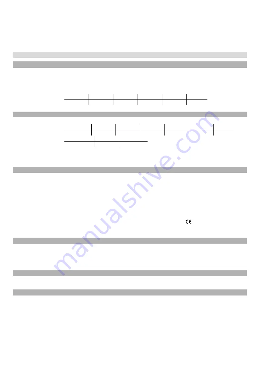
10
…1 MBaud, depending on cable length:
Cable length
< 3 m
< 50 m
< 100 m
< 200 m
< 400 m
Baud rate
1 MBd
< 400 kBd
< 300 kBd
< 200 kBd
< 100 kBd
Measured value
Position
Measurement parameters
Resolution: Position
0.1…100 µm (0.0001…0.1 mm)
Update rate
11
Stroke length
25 mm
300 mm
750 mm
1000 mm
2000 mm
7620 mm
Update rate
10 kHz
3.4 kHz
2.7 kHz
2.1 kHz
1.2 kHz
0.3 kHz
Linearity deviation
12
Stroke length
≤ 400 mm
> 400 mm
Linearity deviation ≤ ±40 μm
< ±0.01 % F.S.
Repeatability
< ±0.001 % F.S. (minimum ±2.5 μm) typical
Hysteresis
< 4 µm typical
Temperature coefficient
< 15 ppm / K typical
Operating conditions
Operating temperature
−40…+85 °C (−40…+185 °F)
Humidity
90 % relative humidity, no condensation
Ingress protection
IP67
(connectors correctly fitted)
Shock test
150 g / 11 ms, IEC standard 60068-2-27
Vibration test
30 g / 10…2000 Hz, IEC standard 60068-2-6 (excluding resonant frequencies) /
RH5-J: 15 g / 10…2000 Hz, IEC standard 60068-2-6 (excluding resonant frequencies)
EMC test
Electromagnetic emission according to EN 61000-6-3
Electromagnetic immunity according to EN 61000-6-2
The sensor meets the requirements of the EC directives and is marked with
Operating pressure
350 bar (5076 psi) / 700 bar (10,153 psi) peak (at 10 × 1 min) for sensor rod, RH5-J: 800 bar (11,603 psi)
Magnet movement velocity
Any
Design / Material
Sensor electronics housing
Aluminum (painted), zinc die cast
Sensor flange
Stainless steel 1.4305 (AISI 303)
Sensor rod
Stainless steel 1.4306 (AISI 304L) / RH5-J: Stainless steel 1.4301 (AISI 304)
Stroke length
25…7620 mm (1…300 in.)
Mechanical mounting
Mounting position
Any
Mounting instruction
Please consult the technical drawings on page 10 and page 11
Electrical connection
Connection type
1 × M16 male connector (7 pin)
Operating voltage
+12…30 VDC
±
20 % (9.6…36 VDC)
Power
consumption
1.2 W typical
Dielectric strength
500 VDC (DC ground to machine ground)
Polarity protection
Up to −36 VDC
Overvoltage protection
Up to 36 VDC
8.2 Technical data Temposonics
®
RH5
10/
With standard one shot of 16 μs
11/
Sensor with standard settings
12/
With position magnet # 251 416-2
Safety Declaration
Dear Customer,
If you return one or several sensors for checking or repair, we need you to sign a safety declaration. The purpose of this declaration is to ensure
that the returned items do not contain residues of harmful substances and / or that people handling these items will not be in danger.
MTS Sensors order number: ________________________________
Serial number(s): _________________________________________
Sensor type(s): __________________________________________
Sensor length(s): ________________________________________
The sensor has been in contact with the following materials:
In the event of suspected penetration of substances into the sensor,
consult MTS Sensors to determine measures to be taken before
shipment.
Do not specify chemical formulas.
Please include safety data sheets of the substances, if applicable.
Short description of malfunction:
Corporate information
Company: _______________________________________________
Address: _______________________________________________
_______________________________________________________
Contact partner
Name: _______________________________________________
Phone: _______________________________________________
E-mail: _______________________________________________
We hereby certify that the measuring equipment has been cleaned and neutralized.
Equipment handling is safe. Personnel exposure to health risks during transport and repair is excluded.
Date
Signature
Stamp
Tel. + 49 - 23 51- 95 87 0
Fax. + 49 - 23 51- 5 64 91
[email protected]
www.mtssensors.com
GERMANY
MTS Sensor Technologie
GmbH & Co.KG
Auf dem Schüffel 9
58513 Lüdenscheid, Germany
USA
MTS Systems Corporation
Sensors Division
3001 Sheldon Drive
Cary, N.C. 27513, USA
Tel. +1 919 677-0100
Fax +1 919 677-0200
[email protected]
www.mtssensors.com


