


Temposonics
®
R-Series
V
SSI
Operation Manual
I 20 I
5. Programming
5.1 Introduction
SSI interface
The synchronous-serial interface (SSI) is a digital interface that
enables serial transmission. Data is transmitted from the device to
the connected controller synchronously to a clock rate specified
by the controller. The interface of Temposonics
®
position sensors
corresponds to SSI industry standard for absolute encoders. Its
displacement value is encoded in a 24 / 25 / 26 bit binary or gray
format and transmitted as a differential signal in SSI standard
(RS-485 / RS-422) – independent of data width of the code
(resolution). The absolute, parallel position data is continually updated
by the sensor and converted by the shift-register into a serial bit
stream. Dependent on the baud rate chosen in the controller the
following cable lengths are possible.
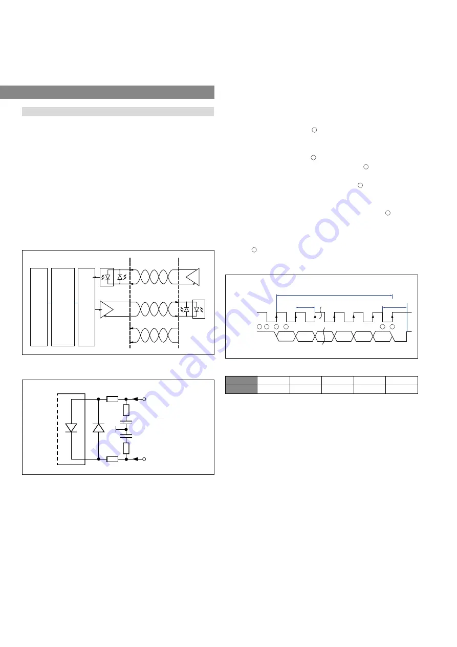
Logic diagram
Sensor
Controller
Clock (+)
Clock (−)
Optocoupler
Driver
Data (+)
Data (−)
+24 VDC
0 V
ASIC for parallel and absolute position data
Microprocessor system
position value = 24 / 25 / 26 bit
binar
y or gray
Shift register
parallel serial converter
Sensor input
100 Ω
7 mA
Clock (+)
100 Ω
LED
100 Ω
Clock (−)
100 Ω
Optocoupler
1.6 V
1 nF
1 nF
Cable length
< 3 m
< 50 m
< 100 m
< 200 m
< 400 m
Baud rate
1 MBd
< 400 kBd
< 300 kBd
< 200 kBd
< 100 kBd
Fig. 24: Schematic connection
Fig. 25: Input wiring clock (+) / clock (−)
Fig. 26: Timing diagram
Fig. 27: Cable lengths and related baud rates
Clock T
Clock break
n * T
MSB: bit n
bit n - 1
bit 3
Clockline
Dataline
High
Low
High
Low
LSB: bit 1
bit 2
1
2
3
4
5
6
The data is transferred serially at SSI, whereby the controller
determines the time of the polling. During data transmission, the
procedure described below is carried out (Fig. 26):
1. In the idle state, when no data is transmitted, the data line and the
clock line are at high level.
1
2. The current position date is frozen in the shift register with the
first falling clock edge. It is no longer possible to update the
position data in this cycle.
2
3. The bit is applied at the following rising edge.
3
4. With the following falling edge, the transmission of the date
begins with the Most Significant Bit (MSB).
4
5. This is repeated for each next lower bit until the Last Significant
Bit (LSB) is transmitted.
6. The clock pause starts after the last falling clock edge
5
. After
the transmission of the LSB, the data line remains on the low
level and the clock line on the high level until the end of the clock
pause. Then the sensor is ready for the transmission of a new
date
6
. The clock break at the end of the transmission is the time
of the standard one shot.


