


Temposonics
®
R-Series
V
SSI
Operation Manual
I 25 I
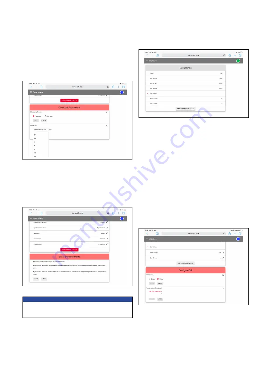
Fig. 42: Configuration of SSI parameters
Fig. 43: Exiting the command mode
After the parameters have been configured, click the EXIT COMMAND
MODE button. A new menu for exiting the command mode will open
(Fig. 43). Click the SAVE AND EXIT button to exit the command mode
and to transfer the changed parameters to the sensor. The sensor
returns to the normal function and outputs the current position value.
The connection icon on the top right will turn to green.
NOTICE
Changes to the sensor parameters must also be set to the controller.
Different parameter values on sensor and controllers can lead to
unpredictable behavior of the controller.
Interface:
Includes information about the interface settings of the
Fig. 44: Configuration of SSI settings
Fig. 45: Configuration of SSI settings
To change interface settings, start the command mode (see above).
After entering the command mode a pencil icon will appear to the
right of the setting values. By clicking the pencil icon a new menu for
configuring the settings will open. Change the parameter and confirm
it by clicking the SUBMIT button (Fig. 45).
• Data Format: Setting the SSI coding for the data transmission
• Data Length: Setting the bit width for the date transmission
• Jitter Window: The jitter specifies the time interval between the
start of measuring and the SSI clock, which is given by the PLC
(for synchronous mode). Values between 0 and 255 µs can be set
for this parameter (default value: 50 µs). A larger value extends the
cycle time of the sensor.
• Error Values: Setting the value which is transmitted in case of a
failure
• Power Failure: Setting the time from when a power failure is output
• Error Counter: Setting the number how often in the case of a failure
(1…255 times) the old measurement value will be repeated, before
the error value will be displayed
After the settings have been configured, click the EXIT COMMAND
MODE button. A new menu for exiting the command mode will open.
Click the SAVE AND EXIT button to exit the command mode and
to transfer the changed settings to the sensor. The sensor returns
to the normal function and outputs the current position value. The
connection icon on the top right will turn to green.
• Resolution: Setting the resolution of the position measurement
• Linearization: Setting the internal linearization (coming soon)
• Enabled: Internal linearization can only be activated if the table
of internal linearization is stored on the sensor
• Disabled: Internal linearization is not activated


