Temposonics
®
R-Series EtherNet/IP
TM
Operation Manual
I
11
I
4.3 Styles and installation of R-Series RH
Temposonics
®
RH
with a pressure resistant stainless steel flange and sensing rod. They are suitable in all fluid power cylinders and externally in
all applications where space is a problem. Position measurement is via ring or U-magnets travelling along the sensing rod without any mechanical
contact.
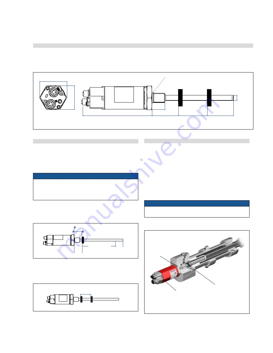
4.3.1 Mounting distances
Active measuring range
The technical data of each sensor is checked as well as documented
and the active stroke length (useful electrical stroke) with its start
and end position is adjusted during final inspection and testing
(see Fig. 11).
NOTICE
On all sensors, the areas left and right of the active stroke length
are provided for mounting and damping of the measuring signal.
They should not be used for measurement, but the active stroke
length can be exceeded without problem.
Mechanical zero
To ensure that the entire measuring range can be used electrically,
the position magnet must be mounted mechanically as follows:
Fig. 12: Temposonics
®
rod with ring magnet
Fig. 11: RH Style dimensional drawing
4.3.2 Installation of RH
Installation of a rod-style sensor
The rod-style version has been developed for direct stroke
measurement in a fluid cylinder.
– Mounted on the bottom of the piston, the ring magnet travels
over the rod contactlessly and marks the position exactly through
the rod wall.
– Inside the pressure-resistant sensor housing immerging into the
open piston rod, the basic sensor is mounted by means of only
two screws. It is the only part that needs replacing if servicing is
required, i.e. the hydraulic circuit remains closed.
NOTICE
After re-installing, securing the basic sensor screws, e.g. using
Loctite 243, is mandatory.
Basic sensor
The electronics head with sensing
element can be replaced via two M4
screws with a 2.5 mm hexagonal
recess, max. tightening torque 1.3 Nm
Pressure-resistant
sensor housing
In the event of servicing,
the rod with the flange
remains in the cylinder.
Fig. 14: Sensor in fluid cylinder
Position magnet
Rod with inner sensor element immersed in the cylinder
Multi-position measurement
The minimum distance between the magnets is 75 mm (3 in.).
Fig. 13: Minimum distance for multi position measurement
Controlling design dimensions are always in metric units and measurements in ( ) are in inches
12
(0.47)
Start position
Magnet slider
U-magnet
Ring magnet
Reference edge of mounting
Start position
Start position
Reference edge of mounting
Reference edge of mounting
28
(1.1)
Measuring range
Measuring range
66
(2.6)
28
(1.1)
51
(2)
51
(2)
63.5/66*
(2.5/2.6)
*>5000 mm measuring range
minimum 75 (3)
minimum 75 (3)
minimum 75 (3)
minimum 75 (3)
minimum 75 (3
61 (2.4)
94
(3.7)
105 (4.13)
not flexible
Reference edge of mounting
Stroke length
61
(2.4)
14
(0.55)
* Tol8 (0.31) / −5 (0.2) up to 7620 (300) stroke length
Tol15 (0.59) / −5 (0.2) > 7620 (300) stroke length
Tolerance of total length has no influence on the stroke length
50
(1.97)
68
(2.68)
35.6
(1.4)
2
(0.08)
49
45
2
Ø 5.5
M5
28
Measuring range
25…5080
66
45
(1.77)
12
(0.47)
66
(2.6)
14.5
(0.57)
45.4 (1.79)
129
(5.07)
28
(1.1)
Measuring range
25…5080
(1…200)
49
(1.93)
9
(0.36)
Ø 5.5 (0.21)
M5 or #10
screw
128
28
50
35.6
68
9.5
O-ring
51
(2)
51
(2)
63.5/66*
(2.5/2.6)
Measuring range
25…7620
(1…300)
Measuring length
100…10060
(4…396)
Measuring length
100…10060
(4…396)
Total length*
133
(5.24)
Ø 10
(Ø 0.39)
46
(1.75)
53
(2)
25
(0.98)
*> 5000 mm
Stroke length
94
(3.7)
133
(5.24)
45
(1.8)
94
(3.7)
45
(1.77)
49
(1.93)
123
(4.84)
7
(0.28)
61
(2.4)
11.5
(0.45)
50 (1.97)
45 (1.77)
123 (4.84)
18
(0.71)
24.7
(0.97)
24.7
(0.97)
8.2
(0.32)
7.7
(0.3)
Ø 6.2
(Ø 0.24)
49
(1.93)
41
(1.61)
45
(1.77)
Null position
Null position
PUR-cable Ø 6 mm
bend radius > 24 mm
PUR-cable Ø 6 mm
bend radius > 24 mm
PUR-cable Ø 6 mm
bend radius > 24 mm
12.7
(0.5)
Null position
Stroke length
25…2540
(1…100)
Stroke length
25…5080
(1…200)
63.5 / 66*
(2.5/2.6)
* > 4500 mm
Stroke length
32
21.4
(0.84)
36.5
(1.44)
32 (1.26)
32
(1.26)
Ø 26.9
(Ø 1.06)
14
14
(0.55)
Ø 26.9
(Ø 1.06)
25
(0.98)
51
(2)
25
(0.98)
O-ring
Rod Type S
Rod Type M
Rod Type C
Ø 18
45
(1.77)
38
(1.5)
Null position
PUR-cable Ø 6 mm
bend radius > 24 mm
Rod Ø 10 (Ø 0.39)
Rod Ø 10 (Ø 0.39)
Rod Ø 10 (Ø 0.39)
12.7
(0.5)
21.4
(0.84)
Measuring length
25…2540
(1…100)
63.5 (2.5)
O-ring
Null position
Null position
63.5 / 66*
* up to 4500 mm
Stroke length
Measuring length
25…5080
(1…200)
PUR-cable Ø 6 mm
bend radius > 24 mm
PUR-cable Ø 6 mm
bend radius > 24 mm
Ø 26.9
(Ø 1.06)
14
(0.55)
14
(0.55)
36.5
(1.44)
32
(1.26)
32 (1.26)
51
(2)
Measuring length
25…5080
(1…200)
51
(2)
25
(0.98)
Rod Type S
Rod Type M
Rod Type C
45
(1.77)
123
(4.84)
24.7
(0.97)
24.7
(0.97)
8.2
(0.32)
7.7
(0.3)
Ø 6.2
(Ø 0.24)
49
(1.93)
45
(1.77)
25
(0.98)
41
(1.61)
63.5 / 66*
(2.5/2.6)
* > 4500 mm
Stroke length
Stroke length
25…5080
(1…200)
51
(2)
36.5
(1.44)
Ø 26.9
(Ø 1.06)
36.5
(1.44)
63.5
(2.5)
63.5 / 66*
(2.5/2.6)
* > 4500 mm
Stroke length
25
(0.98)
36.5 (1.44)
Ø 26.9
(Ø 1.06)
14
(0.55)
Ø 26.9
(Ø 1.06)
32 (1.26)
36.5
(1.44)
Magnet
Magnet
Magnet
Magnet
Magnet
Magnet
Magnet
Magnet
Magnet
Magnet
Magnet
Magnet
Magnet
Magnet
Magnet
Magnet
Magnet
Magnet
Magnet
Magnet
8
± 0.23
(0.31
± 0.01)
8
± 0.23
(0.31
± 0.01)
Rod Ø 10 (Ø 0.39)
Rod Ø 10 (Ø 0.39)
Rod Ø 10 (Ø 0.39)
+0
+0.03
+0
+0.03
Controlling design dimensions are always in metric units and measurements in ( ) are in inches


