


9
Modbus Interface Manual
LP Series
9.1 LP Dashboard
The Modbus implementation for the digital transmitter conforms to
the ‘
Modicon Modbus Protocol Reference Guide, PIMBUS-300 Rev. G
’
available from Modicon, Inc. The information provided below assumes
familiarity with the Modbus protocol as outlined in this reference guide.
All information provided applies to Modbus RTU protocol only.
9.1.1 Installing LP Dashboard
Adjustments to the calibration and setup parameters of the Modbus
interface can be performed using the LP-Series Dashboard. The dash-
board can be run from any Windows 7 or newer OS using a RS485 to
USB converter (MTS part # 380114).
Perform the following steps to install the LP Dashboard and establish
communication:
1. Install setup software from the USB stick that came with the level
transmitter or go to www.mtssensors.com to download the latest
version.
2. Connect level transmitter to RS485 to USB converter, connect
24 Vdc power to the level transmitter, and connect the RS485 to
USB converter to the PC. Example setup shown below.
Fig. 2: Example setup
3. Open LP Dashboard and select Modbus protocol from drop down
menu.
4. Select COM Port. Software will show active COM ports. Make sure
converter is connected before starting LP Dashboard or COM port
will not show.
5. The default address for the level transmitters from the factory is
247. Select address 247. If you do not know the address you can
use the Search function at the bottom of the address range or the
display menu.
Fig. 3: Initial screen
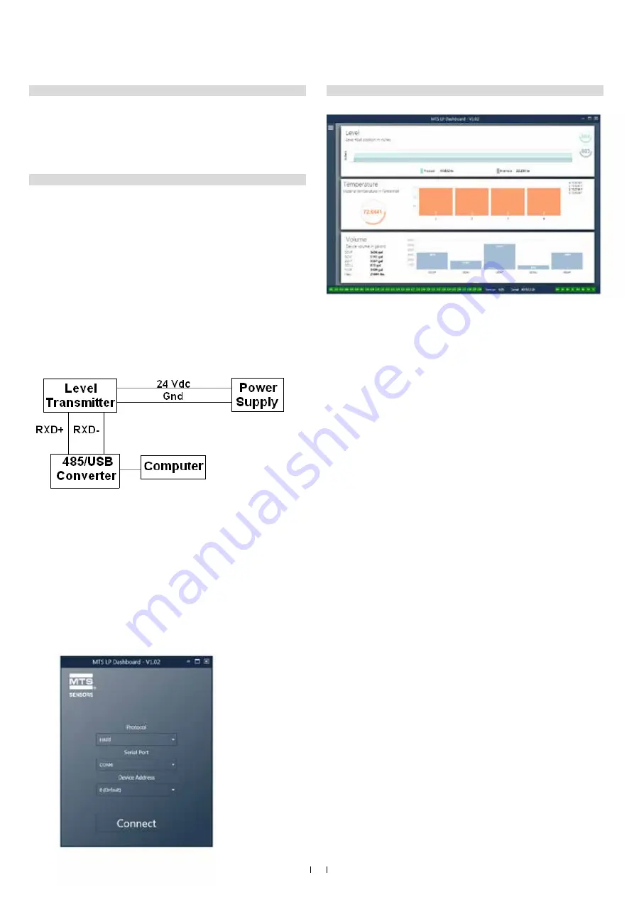
9.1.2 Home screen
Fig. 4: Home screen
The LP Dashboard Home Screen will look different based on whether or
not temperature has been ordered and volume measurement has been
enabled. If the level transmitter includes temperature measurement
and volume measurement is enabled then the Home Screen will look as
shown. If the level transmitter does not include temperature measurement
then the Home Screen will not show the middle panel for temperature. If
the level transmitter does not have volume measurement enabled then the
Home Screen will not show the bottom panel. The Home Screen can be
accessed by pressing the three white bars on the top left.
The level panel on top shows the level measurement for the Product
level and Interface level. If only the product float is selected then only
the product float will be shown. The bold numbers are the numerical
level and the graph is a time lapse of the graphical representation of the
numbers. The red line is the approximate maximum level based off of the
order length of the level transmitter. The numbers on the right of the level
panel are the Trigger Level for the Product Float on top and the Interface
Float on bottom. These are a representation of how strong of a return
signal the level transmitter is experiencing.
The temperature panel will only show if temperature measurement
was ordered and turned on. The left side shows the numerical value of
the average temperature of all temperature sensors below the product
level. The bar graph in the middle of the panel shows each individual
temperature measurement point. Temperature 1 is always the lowest
temperature closest to the bottom of the pipe or hose.
The volume panel is on the bottom. On the left side is the numerical
value for GOVP, GOVI, GOVT, GOVU, NSVP, and mass including units.
The bar graph in the middle is a graphical representation of the volume
measurement.
Across the bottom of the Home Screen is the visual indication of the fault
codes from section 8. Green indicates no fault and red indicates fault.
Next is the firmware version in the middle followed by the serial number.
On the far right are the lights for the soft alarms that can be set in the LP
Dashboard. Green indicates the alarm is not tripped and red indicates that
the alarm has been tripped.


