14
INM4500-2
Mar 2009
MTL4510B modes
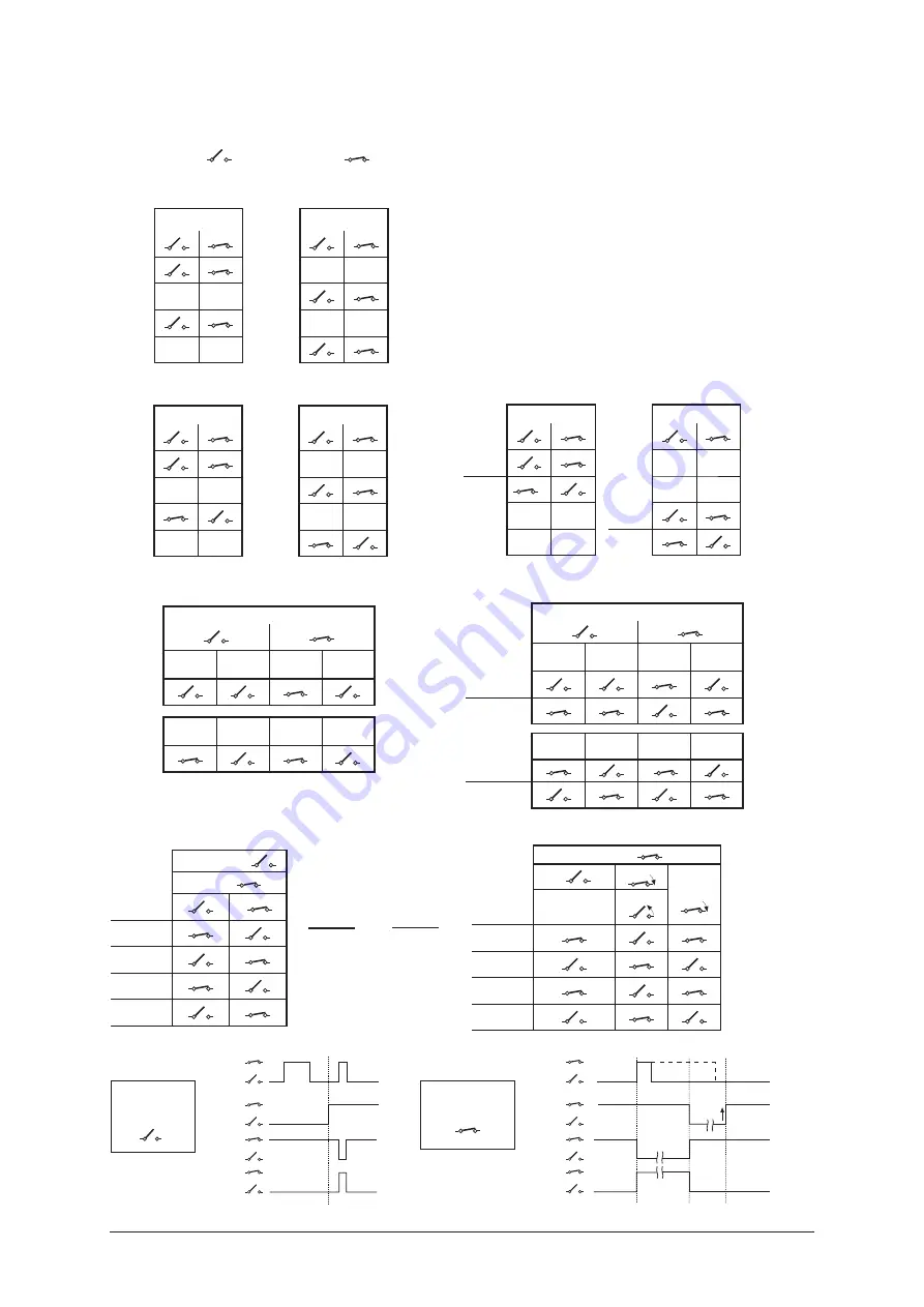
The following logic and timing diagrams are provided to assist the user in understanding the behaviour of the MTL4510B module
when a specific
mode
is chosen.
The open switch (
) and closed switch (
) symbols are used to represent both the input conditions of Ch A, Ch B, Ch C or
Ch D and then the output conditions of o/p 1, 2, 3 or 4.
How to use these mode tables - examples
The logic tables (right) for Mode 1 represent Ch A controlling outputs
1 & 3, while Ch C controls outputs 2 & 4.
Output 1 & 3 are shown following input Ch A (open or closed) while
Outputs 2 & 4 follow input Ch C.
Mode 2 however shows o/p 3 and 4 being in antiphase to their
inputs.
Mode 1
i/p - Ch A
i/p - Ch C
o/p 1
-
-
-
-
o/p 2
o/p 3
-
-
-
-
o/p 4
Mode 2
i/p - Ch A
i/p - Ch C
o/p 1
-
-
-
-
o/p 2
o/p 3
-
-
-
-
o/p 4
Mode 3
i/p - Ch A
i/p - Ch C
o/p 1
-
-
o/p 2
-
-
-
-
o/p 3
-
-
o/p 4
i/p - Ch A
No
fault
Line
fault
No
fault
Line
fault
o/p 1
Mode 4
No
fault
Line
fault
No
fault
Line
fault
o/p 3
i/p - Ch A
No
fault
Line
fault
No
fault
Line
fault
o/p 1
o/p 2
Mode 5
No
fault
Line
fault
No
fault
Line
fault
LFD o/p 3
LFD o/p 4
i/p Ch C
Non-latching
i/p Ch B
Enable
i/p Ch A
o/p 1
o/p 2
o/p 3
o/p 4
Mode 6
i/p Ch C
Latching
i/p Ch A
Start
Reset
i/p Ch B
No effect
Stop
o/p 1
o/p 2
o/p 3
o/p 4
A
Start
B
Stop
i/p Ch A
i/p Ch B
o/p 2&4
o/p 1&3
B
Reset
*
* i/p Ch A can be open or closed when i/p Ch B opens to stop latch
o/p 2&4
o/p 1&3
(enable)
i/p Ch A
i/p Ch B
OR
Non-latching
Ch C open
Latching
Ch C closed
Содержание MTL4500 Series
Страница 1: ...MTL合作伙伴 滨州新大新机电科技有限公司 Instruction Manual INM4500 MTL4500 Series isolating interface units ...
Страница 2: ...ii INM4500 2 Mar 2009 ...
Страница 49: ...45 INM4500 2 Mar 2009 ...
Страница 50: ...46 INM4500 2 Mar 2009 ...
Страница 51: ...47 INM4500 2 Mar 2009 ...


