Operating Manual
English
7
Fitting the steering column
Fig. 2b
Lower part (A) of the steering
column
Press lower part (A) of the
steering column forwards out of
the transport position and attach
with the two supplied screws and
washers (1).
Upper part (B) of the steering
column
Loosen clamping lever (2) anti-
clockwise.
Tilt steering column (B) into the
required position.
Tighten clamping lever (2)
clockwise to lock the steering
column in this position.
Installing the steering wheel
Fig. 2c
Remove cover cap (1, depending
on model) from the steering
wheel. Remove screw (2) and
washer (3 ).
When the wheels are straight,
place the steering wheel on the
steering shaft.
Place on top the washer (3) with
the convex side up, and secure
the steering wheel with the
screw (2).
Insert cover cap (1, depending
on model).
Installing the seat
Fig. 2d
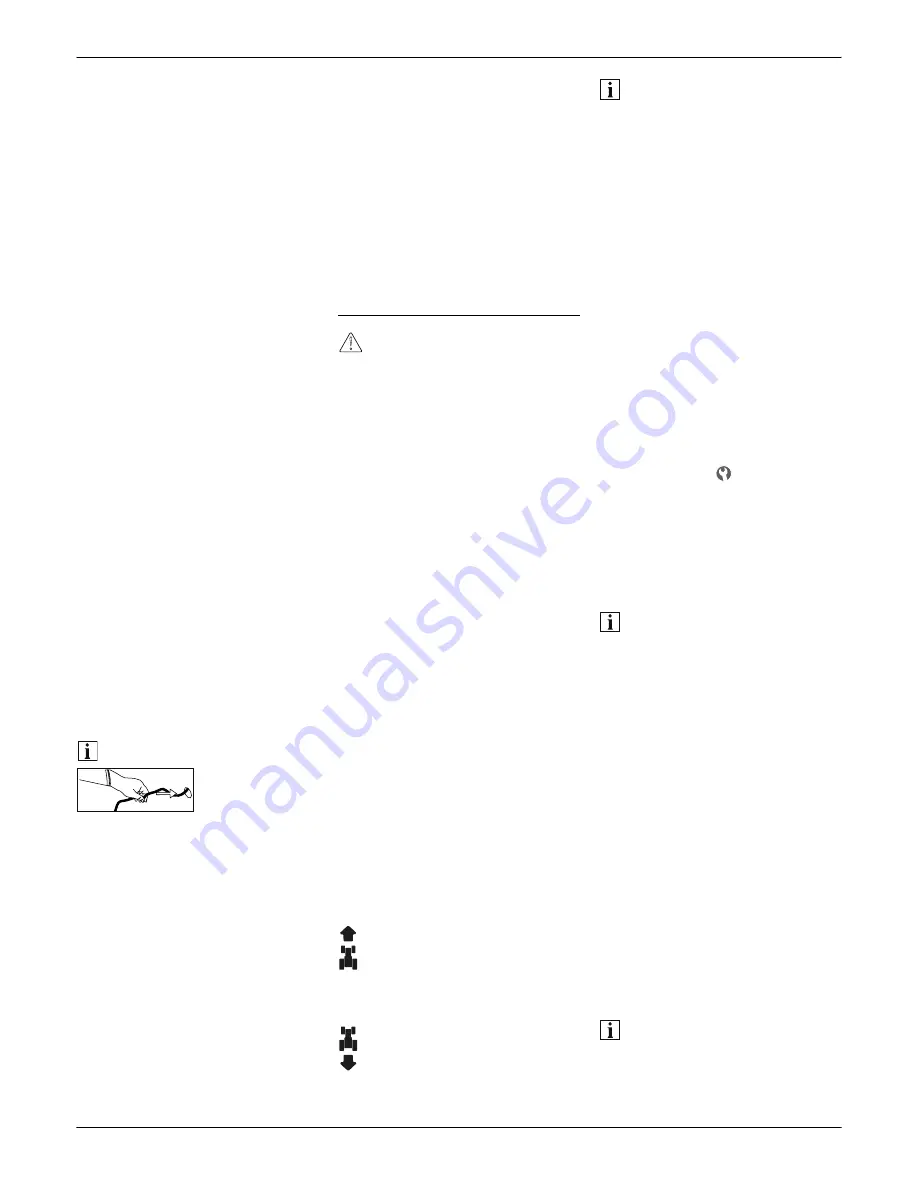
Note
When attaching the seat, do not
damage the seat switch cable!
Push excess cable back into the
opening of the seat support.
Mounting discharge flap on
the cutter deck
Fig. 2e
Remove screws (1) and nuts (2)
from the discharge opening (4)
of the cutter deck.
Attach discharge flap (3) to the
discharge opening (4) using the
screws (1) and nuts (2).
Attaching trailer coupling
(optional)
Fig. 2f
Remove trailer coupling (1) from
the rear panel (4) of the unit
by undoing the screws (2) and
nuts (3).
Rotate trailer coupling (1)
horizontally by 180° and reattach
to the rear panel (4) of the unit
using the screws (2) and nuts (3).
Controls and indicators
Warning. Damage to the unit.
First of all the functions of the
controls and indicators are
described here. Do not execute any
functions yet!
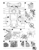
Fig. 1
1 Forward pedal
2 Reverse pedal
3 Clamping lever for steering
column
4 Cutting height adjustment lever
5 Throttle/Choke *
6 Choke *
7 Combination indicator *
8 PTO switch
9 Ignition lock *
10 Fuel tap
11 Fuel tank
12 Tank contents display *
13 Gear release lever
14 Trailer coupling *
15 Can holder
16 Seat adjustment lever *
17 Steering wheel
18 Pedal for parking brake/
cruise control
19 Brake pedal
(* depending on model)
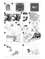
Forward pedal (1)
Fig. 12
The pedal controls the speed
in a forward direction.
Reverse pedal (2)
Fig. 12
The pedal controls the speed
in a reverse direction.
Information on forward/reverse
pedal
To stop or change direction of tra-
vel, release the appropriate pedal.
Clamping lever for steering
column (3)
Fig. 1
Is used to lock the adjustable
steering column.
Cutting height adjustment
lever (4)
Fig. 8
The cutting height adjustment lever
is used to adjust the height of the
cutter deck.
Transport position: Lever in the top
position “T” and engaged in this
position.
Removal/installation position of the
cutter deck: Fixing pin (2) in the
bottom position “ ” and cutting
height adjustment lever engaged
above on the fixing pin.
Mowing position: Insert fixing
pin (2) into the holes marked “1”
to “4” and cutting height adjustment
lever engaged above on the fixing
pin.
Notes
– After inserting the fixing pin, turn
it downwards to prevent it from
coming out of the fixing hole.
In the “mowing position” or
“removal/installation” position the
fixing pin must always be below
the cutting height adjustment
lever which must be correctly
engaged on the fixing pin.
– The “transport position” or
“removal/installation position”
must not be used for mowing,
otherwise the V-belt of the cutter
deck may be damaged.
Press the button (1) on the
cutting height adjustment lever
and pull the lever all the way up
until it engages in the transport
position/“T”.
Select cutting height by fixing the
pin (2) in a hole in the ratchet
plate.
Note
Each hole adjusts the cutter deck by
approx. 6.4 mm. The lowest cutting
height is approx. 3.2 cm and the
tallest cutting height is approx. 10 cm.
Содержание Cub Cadet
Страница 1: ...MTD Products Aktiengesellschaft Saarbrücken Germany E 15 FORM NO 769 10224A ...
Страница 2: ......
Страница 5: ...1 2 18 19 21 20 22 ...


