4-15
BIOS Setup
Full Screen Logo Display
This item enables you to show the company logo on the bootup screen. Settings
are:
[Enabled]
Shows a still image (logo) on the full screen at boot.
[Disabled]
Shows the POST messages at boot.
AddOn ROM Display Mode
This item is used to determine the display mode when an optional ROM is
initialized during POST. When set to [Force BIOS], the display mode used by
AMI BIOS is used. Select [Keep Current] if you want to use the display mode
of optional ROM.
Bootup Num-Lock
This setting is to set the Num Lock status when the system is powered on.
Setting to [On] will turn on the Num Lock key when the system is powered on.
Setting to [Off] will allow users to use the arrow keys on the numeric keypad.
PS/2 Mouse Support
Select [Enabled] if you need to use a PS/2-interfaced mouse in the operating
system.
Wait For
‘
F1
’
If Error
When this setting is set to [Enabled] and the boot sequence encounters an
error, it asks you to press F1. If disabled, the system continues to boot without
waiting for you to press any keys.
Hit
‘
DEL
’
Message Display
Set this option to [Disabled] to prevent the message as follows: Hit Del if you
want to run setup. It will prevent the message from appearing on the first BIOS
screen when the computer boots. Set it to [Enabled] when you want to run the
BIOS Setup Utility.
Interrupt 19 Capture
Interrupt 19 is the software interrupt that handles the boot disk function. When
enabled, this BIOS feature allows the ROM BIOS of these host adaptors to
"capture" Interrupt 19 during the boot process so that drives attached to these
adaptors can function as bootable disks. In addition, it allows you to gain
access to the host adaptor's ROM setup utility, if one is available. When disabled,
the ROM BIOS of these host adaptors will not be able to "capture" Interrupt 19.
Therefore, you will not be able to boot operating systems from any bootable
disks attached to these host adaptors. Nor will you be able to gain access to
their ROM setup utilities.
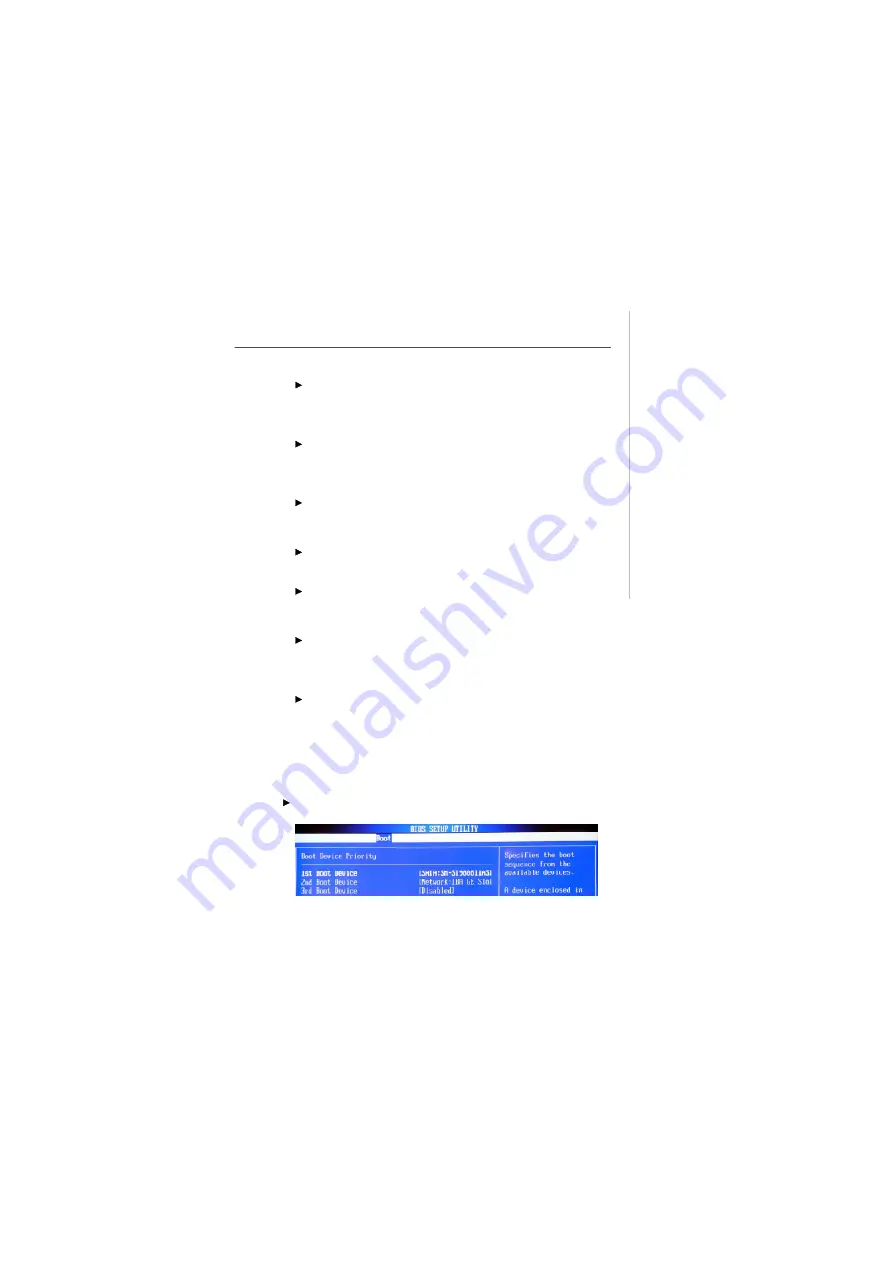
Boot Device Priority
Press <Enter> and the following sub-menu appears:
Содержание MS-9A07
Страница 1: ...MS 9A07 Barebone MS 9A07 V1 X Barebone G52 9A071X1...
Страница 6: ...vi WEEE Statement...
Страница 7: ...vii...
Страница 8: ...viii...
Страница 14: ...MS 9A07 Barebone 1 4 Block Diagram...
Страница 16: ...MS 9A07 Barebone 1 6 Board Dimension...
Страница 17: ...1 7 Product Overview System Dimension...
Страница 20: ...MS 9A07 Barebone 1 10...
Страница 42: ...MS 9A07 Barebone 3 8 Step 4 Connect the SATA power and data cable...
Страница 44: ...MS 9A07 Barebone 3 10...
Страница 50: ...4 6 MS 9A07 Barebone Advanced CPU Configuration Press Enter and the following sub menu appears...
Страница 67: ...5 3 System Resources AMI POST Code...
Страница 68: ...MS 9A07 Barebone 5 4...
Страница 69: ...5 5 System Resources...
Страница 70: ...MS 9A07 Barebone 5 6...


