


English
Operation manual
7
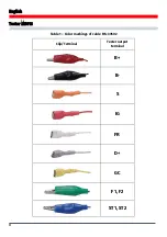
The diagnostic cable for voltage regulators (Fig.4) has the following color markings (Table 1):
•
Red cable with a clip –
B+
– voltage regulator terminal B+ (terminal 30);
•
Black cable with a clip –
B-
– voltage regulator terminal B- (GND, terminal 31);
•
Orange cable with a terminal –
S
(Sense pin) – through this terminal, the voltage
regulator measures the battery voltage and compares it with the alternator/voltage
regulator output voltage. This cable is connected to terminals S of the voltage regulator;
•
Red cable with a terminal –
IG
(Ignition) – the ignition terminal (terminal 15, A, IG);
•
White cable with a terminal –
FR
– through this terminal, the data on the voltage
regulator load are transmitted. The cable connects to FR, DFM, and M terminals of the
voltage regulator;
•
Grey cable with a terminal –
D+
– the terminal through which the control lamp of the
voltage regulator is connected to terminals D+, L, IL, and 61 of the voltage regulator;
•
Yellow cable with a terminal –
GC
– for connection of the tester to the control channel
of the voltage regulator through voltage regulator terminals COM, SIG, and others;
•
Green cables with clips –
F1, F2
– for connection of the tester to the brushes of the voltage
regulator or their corresponding terminals: DF, F, FLD;
•
Blue cables with clips –
ST1, ST2
– for connection of the tester to the stator terminals of
the voltage regulator: P, S, STA, Stator.
Содержание MS016
Страница 2: ......
Страница 105: ...MS016 105 ...
Страница 106: ...MS016 106 ...
Страница 108: ...MS016 108 ...
Страница 109: ...MS016 109 ...
Страница 110: ...MS016 110 ...
Страница 111: ...MS016 111 ...
Страница 112: ...MS016 112 ...
Страница 113: ...MS016 113 ...
Страница 114: ...MS016 114 ...
Страница 115: ...NOTES 115 ...
Страница 116: ......


