


English
Operation manual
25
4. Turn off simulation of the alternator rotation by pressing K15 and setting rpm to zero. The
control lamp indicator (Fig.10, n.10) will light up. Press K15 again to restart simulation, the control
lamp indicator must go out.
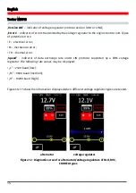
5. Adjust the preset stabilizing voltage in the range from 13.2 to 14.5 volts. The measured voltage
must vary in proportion to the pre-set one.
6. Press BACK to exit the test mode. Disconnect the clamps form the voltage regulator.
7. Failure to perform as described in sub-items 3-5 indicates the voltage regulator malfunction.
4.4. Diagnostics of voltage regulators of C JAPAN type
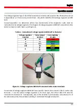
1. Connect the voltage regulator as described in item 4.1.
2. Select and activate the test mode (Fig.9) for regulators of C JAPAN type.
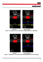
3. In diagnostic mode the stabilizing voltage must set in the range from 14 to 14.5 volts.
4. Press K15 and set rpm to zero to stop simulation of the alternator rotation. The control lamp
indicator (Fig.10, n.10) must light up. Press K15 once again to turn the simulation on – the control
lamp indicator will go out.
5. Switch the preset stabilizing voltage to OFF. The measured stabilizing voltage must set in the
range from 12 to 12.7 volts.
6. If the voltage regulator is equipped with terminal S, press SENSE to check its operability – the
stabilizing voltage must increase. Press SENSE once again, the stabilizing voltage must decrease
to its initial values.
7. Press BACK to exit the test mode. Disconnect the clips from the voltage regulator.
8. Failure to perform as described in sub-items 3-5 signals the voltage regulator malfunction.
4.5. Diagnostics of voltage regulators of SIG and P/D types
1. Connect the voltage regulator as described in item 4.1
2. Enter the menu for voltage regulator type selection (Fig.9), select the nominal voltage and
activate the test mode that corresponds to the type of the tested voltage regulator.
3. Upon diagnostic mode activation, the stabilizing voltage must set at 13.8V, the allowable
deviation is ±0,2V.
Содержание MS016
Страница 2: ......
Страница 105: ...MS016 105 ...
Страница 106: ...MS016 106 ...
Страница 108: ...MS016 108 ...
Страница 109: ...MS016 109 ...
Страница 110: ...MS016 110 ...
Страница 111: ...MS016 111 ...
Страница 112: ...MS016 112 ...
Страница 113: ...MS016 113 ...
Страница 114: ...MS016 114 ...
Страница 115: ...NOTES 115 ...
Страница 116: ......


