8
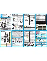
Transformer
Liquid Level
Control Board
Water Feed
Solenoid
Water Feed
Thermostat
Liquid Level Probe
Power Block
Power Supply
Knock-Out
Contactor
Steam Outlet
Fuses
AutoFlush Plug and
Play Connector
(see page 11)
Transformer
Liquid Level
Control Board
Water Feed
Solenoid
Water Feed
AutoFlush Plug and
Play Connector
(see page 11)
Thermostat
Liquid Level Probe
Power Supply
Knock-Out
Contactor
Steam Outlet
FIELD POWER WIRING
TO AVOID EQUIPMENT DAMAGE DO
NOT CONNECT POWER SUPPLY
DIRECTLY TO ELEMENTS!!!
L1, L2, GROUND TO BE FIELD WIRED
NOTE: FOR ILLUSTRATIVE PURPOSES
ONLY. CONSULT WITH QUALIFIED
LICENSED ELECTRICIAN FOR
ELECTRICAL INSTALLATION.
Models CT6E – CT9E
(single phase wiring shown)
Models CT
12
E
(single phase wiring shown)
ELECTRICAL
All electrical wiring to be installed by a qualified licensed electrician
in accordance with National Electrical Code and local electrical code.
Power Wiring-
See “Field Power Wiring” Diagrams (below)
1.
Check power voltage. Use 240V rated unit when supply is greater
than 208V. Use 208V rated unit for 208V power.
2.
Use minimum 90˚ C/300V rated insulated copper conductors only,
sized in accordance with National Electrical Code and local electri-
cal code for the current in Ampere Chart. If allowed by codes, NM
cable may require a larger wire size than as listed on the chart.
3.
Connect suitably sized equipment grounding wire to ground termi-
nal provided.
4.
Install a separate circuit breaker between supply and unit. Provide
a power supply disconnect within sight of the steam generator or
one that is capable of being locked in the open position.
5.
For single phase units, use two-wire supply source and equipment
grounding wire. Neutral (white) wire is not required.
CHART
________________________________________________________________________
MODEL
MAX ROOM
KW
VOLTS
WIRE SIZE
NO.
VOL
(CU. FT.*)
1
PH
†
PHASE
AMPS
(AWG)
________________________________________________________________________
208
1
29
8
CT6E
150
6.0
3
17
10
________________________________________
240
1
25
8
3
14
12
________________________________________________________________________
208
1
44
8
CT9E
360
9.0
3
25
8
________________________________________
240
1
38
8
3
22
10
________________________________________________________________________
208
1
58
6
CT2E
575
12.0
3
34
8
________________________________________
240
1
50
6
3
29
8
________________________________________________________________________
*See page 2 for room sizing.
†
All specifications shown are for 208V and 240V.
Consult factory for other voltage specifications.
mr
.
steam
®
club therapy
®
Installation, Operation & Maintenance Manual
______________________________________________________________________________
!
WA R N I N G
Provide a power supply disconnect within sight of the steam generator or one
that is capable of being locked in the open position as permitted by code.