7
High-Tech Made in Switzerland
MCDISK-E
2.3 SET-UP
This chapter provides the information required to configure
the MCDISK-E reader/writer. It describes the setting of the
SCSI ID, local features and configuring the SCSI termination
characteristics.
If you have any doubts on configuration, contact your
MCDISK-E supplier or an authorized dealer of your host
computer.
WARNING: Before you begin, review and observe
the safety precautions described at the beginning of
this manual to avoid personal injury or damage to
equipment.
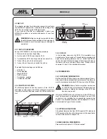
2.3.1 SET-UP OVERVIEW
Set-up of MCDISK-E-1 is a step by step procedure:
1. Remove the drive from its packing and place it on an
appropriate antistatic work surface, following the ESD
precautions described in the beginning of this manual.
2. Set the unit’s SCSI ID and optional features.
3. Terminate the SCSI bus if required.
4. Mount the unit in the system (see chapter 2.6).
5. Connect DC power and SCSI bus to the unit (see chapter
2.5).
The default factory settings are as follows:
•
SCSI ID = 3
•
Parity disabled
•
Single SCSI ID
•
Full CIS mode
•
Termination enabled
•
Termpower enabled
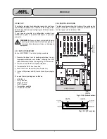
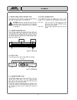
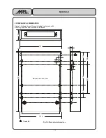
Fig. 2.3.2.A: Parts location
Power LED
(green)
Lower card
eject button
Error LED
(red)
Upper card
eject button
Access LED
upper slot
Access LED
lower slot
Fig. 2.3.2.B: Front view
2.3.2 PARTS LOCATIONS
The following figures show the location of the configuration
jumper, connectors, termination resistors as well as a view of
the front panel with its indicator LEDs.
5
5
&
&
&
&
5
5
/
/
'
'
)
-
5
5
5
5
&
&
&
-
&
5
'
)
&
'
&
&
&
&
&
&
7
5
&
&
5
5
7
&
&
&
&
&
5
5
5
&
&
&
&
&
&
&
8
8
&
&
&
5
5
7
7
&
&
&
&
5
5
7
5
5
&
7
'
7
5
5
7
&
'
5
5
5
5
&
8
5
5
5
5
8
5
5
5
5
5
5
&
8
&
&
&
&
5 5 5 5
5
5
5
& 5
&
5
5
7
&
&
5
&
73
73
5
5
5
5
&
5
5
&
&
&
5
5
&
&
5
5
5
5
5
5
&
5 5 5
J3: SCSI connector
J
2
: SCSI ID a
n
d
o
p
tion
al f
eat
ures
J6: Power
connector
J8: SCSI termination
& termination power


