For maximum rigidity and lower noise levels the base
plate should be grouted to the foundation after the anchor
bolts have been evenly tightened. A good grade of non-
shrink grout is recommended. The spaces between the base
plate and the foundation around the shims should also be
filled with grout. Allow the grout to dry according to manufac-
turer’s instructions, then fully tighten the anchor bolts.
2-7. SHAFT ALIGNMENT
Although the base-mounted units supplied by Robbins &
Myers are leveled with respect to the base before shipping,
most of the larger pump and driver units are shipped with the
flexible coupling disconnected.
After the base has been bolted down to the foundation,
check the following conditions:
2-8. On coupling connected units,
be sure that the pump
and driver shafts are realigned before the coupling is con-
nected. Care should be exercised to ensure that all compo-
nents are level and mounted in a direct line.
Check gap between coupling halves (refer to coupling
manufacturers recommendations). Adjustment can usually
be accomplished by loosening the mounting bolts on either
the pump or driver and moving the loosened component into
alignment with the fixed component. On couplings with equal
diameter hubs, it may be helpful to lay a straight edge axially
across the coupling halves to check alignment.
2-9. On belt drive units,
check to ensure that sheaves or
sprockets are in alignment. Check belts for proper tension.
Tension requirements will vary with type of belt, center dis-
tances, and belt speeds. Consult belt manufacturer for spe-
cific recommendation.
2-10. WATER FLUSH OF PACKING
The packing may be either grease lubricated through a
grease fitting in the stuffing box or have plumbing connected
to the housing to allow a water flush. Packing is not grease
lubricated at the factory prior to shipping.
When the material being pumped is abrasive, water flush-
ing the packing is recommended to extend shaft life.
Clean water can be injected through a 1/8” NPT tapped
hole that normally houses the grease fitting for lubricating the
packing. The water can be permitted to leak axially along the
shaft in either direction or can be removed from the second
tapped hole in the stuffing box. In both cases, the discharge
from the stuffing box should be throttled slightly to maintain
10-15 PSI higher pressure in the stuffing box than is present
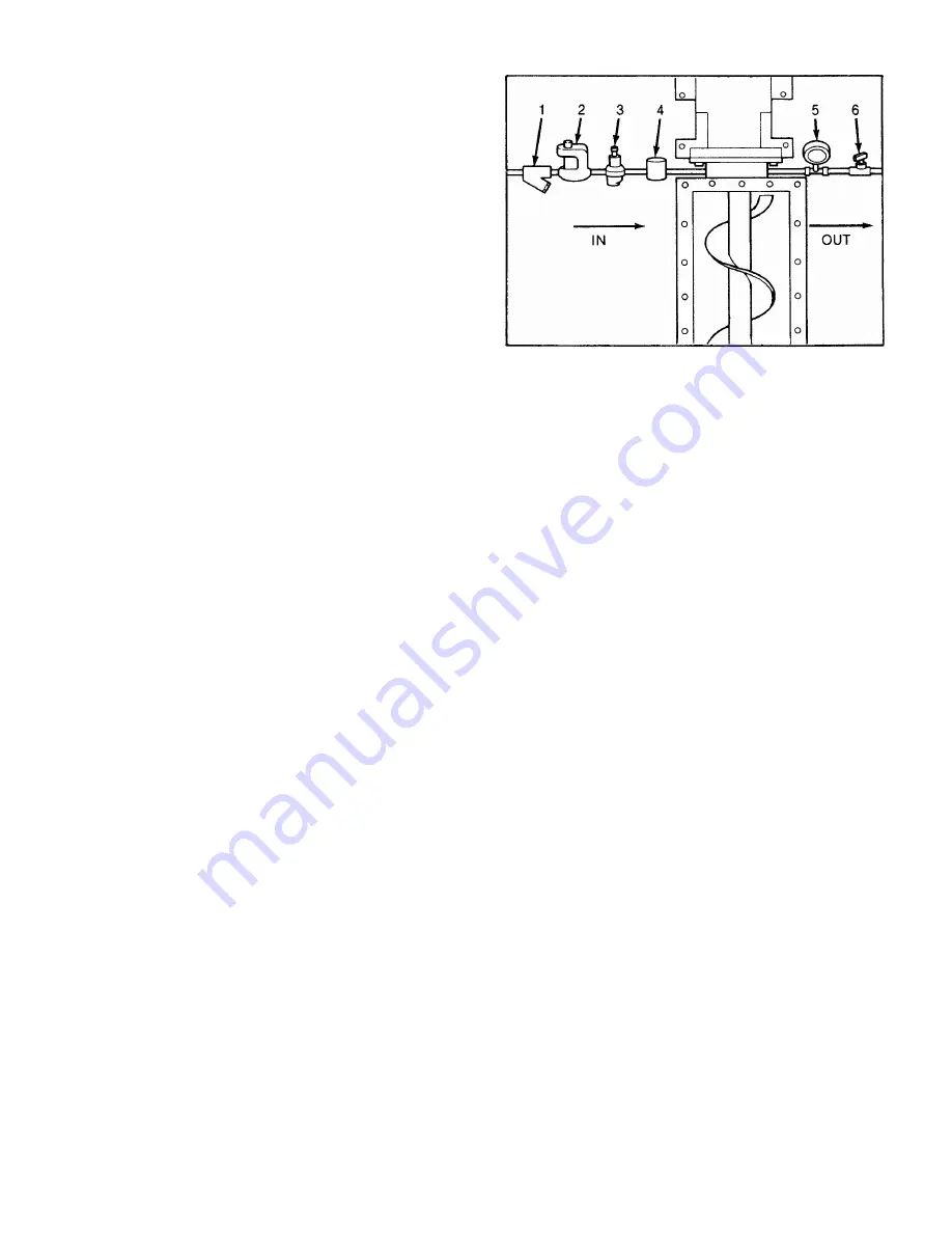
in the suction housing. (See fig. 2-2.) Flow rate should be
approximately 1/2-2 gpm.
If mechanical seals are to be used on the unit, consult the
seal manufacturers’ instructions for seal flush requirements.
3-1. OPERATION
3-2. INITIAL CHECK
Before putting the pump into operation, the following items
should be checked to ensure that each piece of equipment is
installed correctly:
—
Pump, driver, coupling or sheave alignment.
Page 3
Figure 2-2. Typical water flush arrangement for units
with packing includes strainer valve (1), sight flow meter
(2), pressure regulating valve (3), solenoid valve (4),
pressure gauge (5), and needle valve (6).
—
Electrical
connections
— Gauges and other instruments.
— Water flush connection to the stuffing box.
—
Pump
rotation.
Normal rotation is indicated on the
nameplate on the bearing housing.
— All valves should be open on both suction and
discharge sides of pump.
CAUTION: This is a positive displacement pump. Do not
operate it
against a closed valve.
3-3. START-UP
CAUTION: DRY OPERATION IS HARMFUL TO THE PUMP!
Never allow the pump to operate without liquid,
as dry operation will cause premature wear of
the stator and possible damage. The stator is
lubricated by the liquid which is pumped.
1. Before operating the pump for the first time, fill it with
liquid (the pipe plug tap on the suction housing may be used
for filling). If the liquid to be pumped is highly viscous, dilute
it before filling the pump. The liquid fill-up will lubricate the
stator for the initial start-up.
Note: If the pump is shut down temporarily, enough liquid
will remain in the system to provide lubrication upon
restarting. It is advisable to maintain the suction pip-
ing at a higher elevation than the centerline of the
pump in order to contain some liquid in the pump at
time of shutdown.
2. Once the pump has been filled with liquid, check for di-
rection of pump rotation by momentarily starting and stop-
ping the drive. Check rotation arrow on pump nameplate for
correct rotation.
3. If applicable, turn on the seal water to packing.
4. Start pump.
3-4. PACKING LEAKAGE
A packed stuffing box is designed to control leakage, not
stop it completely. Leakage is generally necessary to reduce
friction and dissipate heat. The amount of leakage necessary
will depend on the fluid pumped, the installation, and pump
speed and type. Refer to Section 4-3 for packing adjustment.
Содержание Version 3
Страница 1: ......
Страница 2: ...MOYNO 2000 Pumps G2 Open Throat Models G3 Bridge Breaker Models Version 3 Models SERVICE MANUAL ...
Страница 19: ...Page 16 4 60 PARTS LIST FOR G2 OPEN THROAT Table 4 1 G2 Parts List ...
Страница 20: ...Page 17 FOLD OUT FOR EXPLODED VIEW OF PUMP Notes ...
Страница 21: ...Page 18 ...
Страница 22: ...Page 19 Figure 4 7 G2 open throat pump exploded view ...
Страница 26: ...Page 23 Figure 4 10 G3 bridge breaker exploded view ...
Страница 28: ...Page 25 ...


