Page 2
The first letter identifies the material of the suction
housing.
C
—
Cast
Iron
E
—
Carpenter 20 Stainless Steel
H
—
Hastelloy
“C”
M
—
Monel
S
—
316 Stainless Steel
W
—
Cast
Steel
X
—
Special to application
Note: The bearing housing of the pump is always made
of cast iron.
The second letter indicates the material used in the
drive shaft, connecting rod, rotor and other wettable parts.
D
—
Alloy
Steel
E
—
Carpenter 20 Stainless Steel
G
—
416 Stainless Steel
H
—
Hastelloy
“C”
J
—
17-4 PH Stainless Steel
M
—
Monel
S
—
316 Stainless Steel
X
—
Special to application
The third letter indicates the material of the stator. It identi-
fies only the stator material and not that of the tube in which
the stator is placed, which is always carbon steel. Standard
stator materials used in the Moyno 2000 pump are as fol-
lows:
B
—
EPDM 300, 70 Durometer
C
—
Nitrile 103, 50 Durometer
D
—
Tool
Steel
E
—
Nitrile 110, 70 Durometer
F
—
Fluoroelastomer 500, 75 Durometer
G
—
416 Stainless Steel
H
—
Hastelloy
“C”
J
—
17-4 PH Stainless Steel
K
—
Hypalon 800, 70 Durometer
M
—
Nitrile 100M 70 Durometer
P
—
Thiokol 70 Durometer
Q
—
Nitrile 100, 70 Durometer
R
—
Natural Rubber 200, 55 Durometer
T
—
Teflon 15% glass
U
—
Urethane 70 Durometer
X
—
Special to application
Z
—
White Nitrile 150,70 Durometer
A typical type designation such as CDQ, would identify the
following materials of construction:
C
=
Cast iron suction housing
D
=
Alloy steel rotor, drive shaft, connecting
rod and other minor metallic parts in con-
tact with the fluid being pumped.
Q
=
Nitrite (70 durometer) stator
1-8. Trim Code.
Also included in the Model Number is the
three character Trim Code which is used to identify pump
construction. The letters “AAA” signify standard construction,
with letters other than “A” signifying variations. The first letter
identifies sealing variations; the second, internal variations;
and the third, rotor variations.
1-9. Variations of Standard Parts.
Refer to Sections 4-55
thru 4-57 for variations available for modifying pumps to
meet specialized pumping conditions. If the trim code of your
pump is other than “AAA,” contact your nearest Moyno rep-
resentative for clarification. Do not modify your pump with
any variation unless you have determined that it is compat-
ible with your application.
2-1. INSTALLATION
2.2. GENERAL
Moyno pumps are lubricated and tested at the factory
prior to shipment and require minimum pre-start up
maintenance.
Accessibility to the pump and adequate clearance should
be a prime consideration in any installation. Enough space
should surround the unit so that maintenance can be car-
ried out with ease.
2-3. PIPING
2-4. Suction hopper
used with open throat and bridge
breaker pumps should have nearly vertical sides, or be oth-
erwise designed to enhance the flow of the material into the
pump.
2-5. Discharge piping
diameter should generally be as
large as the pump ports unless fluid conditions indicate
otherwise.
An easily removable section of piping one-to-two times
longer than the connecting rod should be mated to the dis-
charge port. This will allow the rotor and stator to be re-
moved without having to remove the complete pump from
the base.
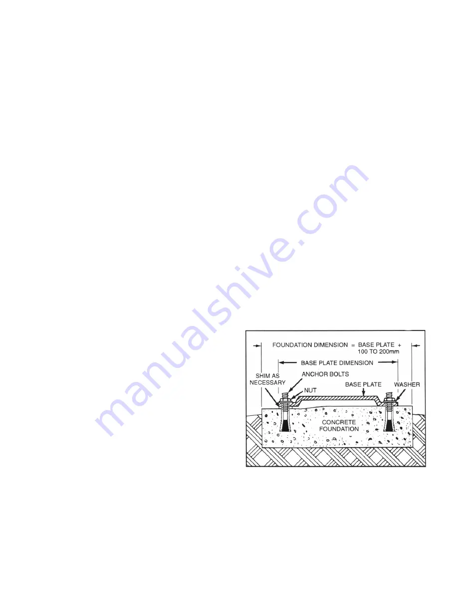
2-6. FOUNDATION
For maximum pump-driver unit life, each unit should be
mounted on a strong, fabricated-steel base plate which can
be ordered from Moyno. The base plate should be mounted
on a concrete foundation built on a solid base. The foundation
should be approximately 4” to 8” longer and wider than the
base for which it is built. (See fig. 2-1.) Anchor bolts for the
base plate should be located in the foundation.
Figure 2-1. Typical Foundation Example
Check the base plate surface with a carpenter’s level
and place shims under the base plate at the places
necessary to make it level. Then check the pump,
driver shaft and the pump ports to ensure that they are level.
Complete base mounted units supplied by Moyno including
pump and driver are leveled with respect to the base at the
factory. Shifting may occur during shipment. The pump and
driver should be realigned. Care should be exercised to en-
sure that all components are level and mounted in a direct line.
Содержание Version 3
Страница 1: ......
Страница 2: ...MOYNO 2000 Pumps G2 Open Throat Models G3 Bridge Breaker Models Version 3 Models SERVICE MANUAL ...
Страница 19: ...Page 16 4 60 PARTS LIST FOR G2 OPEN THROAT Table 4 1 G2 Parts List ...
Страница 20: ...Page 17 FOLD OUT FOR EXPLODED VIEW OF PUMP Notes ...
Страница 21: ...Page 18 ...
Страница 22: ...Page 19 Figure 4 7 G2 open throat pump exploded view ...
Страница 26: ...Page 23 Figure 4 10 G3 bridge breaker exploded view ...
Страница 28: ...Page 25 ...


