background image

4

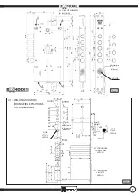
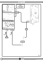
Fig.1

A

A

B

B

B

B

A

A

C

99348ENG - XMODE / XMODE1 - MANUALE INSTALLATORE - REV. 01

A = SIDE ATTACHEMENTS

B = BUSHINGS

C = MORTISE-TYPE

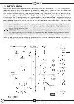
2 - INSTALLATION 

Fix the lock to the door structure by using all of the fasteners: side attachments (A), bushings (B) or mortise-type (C) (Fig. 1-2). In order to work correctly, 
the lock should be fixed in a vertical position. The lock may not work properly if installed or used in a different position. For correct operation of the 
lock, the spring latch must be able to protrude freely without frictioning when the door is open or closed.
If necessary, drill spaces in the door structure to hold the battery pack and the box for the electronic board (supplied in the pack for the selected 
version) in a non-binding position defined only by the length of the wires and by internal dimensions due to door configuration (opening limiter, 
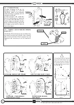
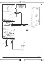
switchlocks, etc.). Drill the frame for the door status sensor. For these drillings, see the attached mounting diagram in Fig. 3. If you are mounting 
switchlocks, always provide sufficient clearance between the bar and the upper and lower tabs both when the lock is open and when it is closed, so 
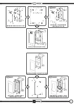
as to prevent strain that could damage the motor. Fasten the battery pack, if required, and wire it as shown in paragraphs 3, 4, 5, 6 (diagrams Fig.3RH 
page 14), (depending on door version), preparing the connections for the board holder, lock and the internal and external escutcheons using the 
wires supplied as standard.

If a mains powered connection is provided, it is advisable to use grommet 99144 (not included) between fixed upright and leaf, attaching it as 
shown in the detail (Fig. 3RH) and instructions attached to the grommet pack.

Protect the lock before doing any work on the door that could produce waste material (soldering, drilling of panels, drilling of structure, 
etc.) that might enter the lock and impair its functioning. Do not insert the batteries into the battery holder until finished fixing to avoid 
short circuits that may damage the system.

WARNING!

 When the door is completely mounted and perfectly positioned, run the first checks on the lock (opening/closing) in mecha-

nical mode to make sure there is no frictioning on the levers (bars/switchlocks) or on the key when turning.
These problems could impair correct electronic operation of the lock and cause permanent malfunction. Mottura Serrature di Sicurezza 
S.p.A. declines all liability if this procedure is not performed and, in such case, all warranties on the product will lapse.

Variation in 

bolt centre 

distances

SENSOR

Содержание XMODE

Страница 1: ...POWERED ELECTRONIC LOCK INSTALLATION INSTRUCTIONS RECHARGEABLE...

Страница 2: ...2 3 XMODE1 QUICK RELEASE VERSION 3 ESCUTCHEONS 6 3 1 ESCUTCHEON ATTACHMENT DRILLING DIAGRAM 3 2 TYPES OF ESCUTCHEONS 4 CONNECTING REMOTE CONTROL DEVICES 9 4 1 EXTERNAL PERIPHERAL VOLTAGE FREE CONTACT...

Страница 3: ...ice personnel The warranty covers the replacement or repair of parts found defective at origin due to manufacturing defects Costs of shipping to and from service centers will be paid by the customer I...

Страница 4: ...t could damage the motor Fasten the battery pack if required and wire it as shown in paragraphs 3 4 5 6 diagrams Fig 3RH page 14 depending on door version preparing the connections for the board holde...

Страница 5: ...RTISE TYPE SENSOR Variation in bolt centre distances DOOR STATUS SENSOR DOOR STATUS SENSOR Variation in bolt centre distances BATTERY HOLDER DOUBLE TUBE VERSION BATTERY HOLDER CASSETTE VERSION 2 1 DRI...

Страница 6: ...catalogs Alternatively use European cylinder with the dimension shown in the diagram OUTSIDE plate screw 2 3 XMODE1 QUICK RELEASE VERSION CODE XTH Thelockboltsinthequick releaseversionareunlockedusin...

Страница 7: ...RD VERSION ART 99 741 KEYBOARD TRANSPONDER VERSION ART 99 736 DISPLAY VERSION ART 99 742 KEYBOARD VERSION ART 99 760 KEYBOARD TRANSPONDER VERSION ART 99 749 FINGERPRINT SCANNER TRAN SPONDER VERSION AR...

Страница 8: ...llic escutcheon cover which is available in different finishes Some escutcheons require an IP54 protection rating 3 2 TYPES OF ESCUTCHEONS OUTSIDE DOOR KEYBOARD TRANSPONDER VERSION ART 99 686 FINGERPR...

Страница 9: ...door and the device with the coil connected to the remote control and the Common and Normally Open contacts of the relay connected to the lock with cable 99 701 The cable has to run through a grommet...

Страница 10: ...AC main power supply cables longer and the lock 12 VDC power supply cables shorter in order to minimise voltage drop along the cable In case you must use longer lock power supply cables never exceed 1...

Страница 11: ...Fig B 230Vca 12Vcc 99 703 Wired tube battery pack 99 704 Wired cassette battery pack BATTERY PACK WIRING battery pack wire 99 683 AC DC Adapter see chapter 7 cable 99 697 Grommet 99 144 WIRING MAINS...

Страница 12: ...48ENG XMODE XMODE1 MANUALE INSTALLATORE REV 01 99 683 AC DC Adapter see chapter 7 99 703 Wired tube battery pack 99 704 Wired cassette battery pack battery pack wire WIRING MAINS POWERED BATTERIES cab...

Страница 13: ...683 AC DC Adapter see chapter 7 99 711 Battery charger 99 703 Wired tube battery pack 99 704 Wired cassette battery pack battery pack wire WIRING MAINS POWERED RECHARGEABLE BATTERIES cable 99 697 cab...

Страница 14: ...version LH is specular FOR SPECIFIC WIRINGS SEE PARAGRAPHS 3 4 5 6 6 ELECTRICAL WIRING N B Escutcheons vary de pending on the selected configuration see paragraph 3 External Escutcheon EXTERNAL PERIPH...

Страница 15: ...TION INPUT Connect the 230VAC 50 60Hz home power supply to input terminals L and N inserting a cut out and two way switch up line Connect the ground of the power supply to the input terminal with the...

Страница 16: ...WORK TEMPERATURE Min 10 C Max 40 C ENCAPSULATED TRANSFORMER PROTECTION T 0 125 A MECHANICAL WEIGHT 0 7 Kg DIMENSIONS 142 x 110 x 62 mm MATERIAL Blend PC ABS self extinguishing UL94 V0 OUTPUT VOLTAGE 1...

Отзывы: