2
1
2
4
5
94415
94416
6
7
6-A
3
99342ENG - REV. 00
LOCK INSTALLATION
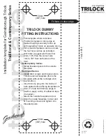
In case of a new installation use the supplied template.
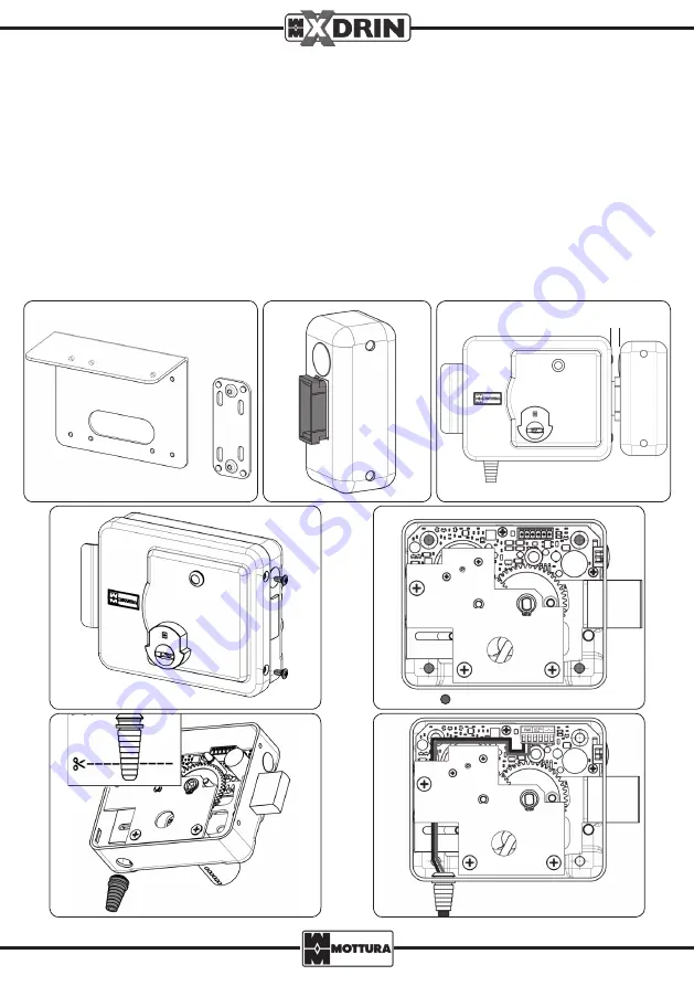
Solder or fasten the optional plates (code 94415/94416 - Fig. 1) to the gate structure and temporarily position the lock
and strike plate. To position the strike plate correctly, use the supplied plastic template (Fig. 2), bearing in mind that
the distance between the lock and the strike plate must not exceed 10 mm (Fig. 3).
If replacing an existing electric lock, fasten the XDRIN lock using the existing plates/holes.
Mount the lock according to the following procedure:
- Unscrew the side screws and remove the cover (Fig. 4).
- Attach the lock and the strike plate using the supplied screws (Fig. 5).
- Cut the supplied graduated sleeved grommet (Fig. 6 - A) in order to have the right diameter for the entering power
supply cable, then insert the grommet into its designated hole at the bottom of the lock (Fig. 6).
- Insert the cable and pull it through to the terminal block attached to the electronic board by passing it under the gear
assembly plate (Fig. 7) and following the electrical connection diagrams shown in these instructions.
- Replace the cover and test the lock.
FASTENING HOLES
10 mm MAX


