3
DESCRIPTION OF COMPONENTS
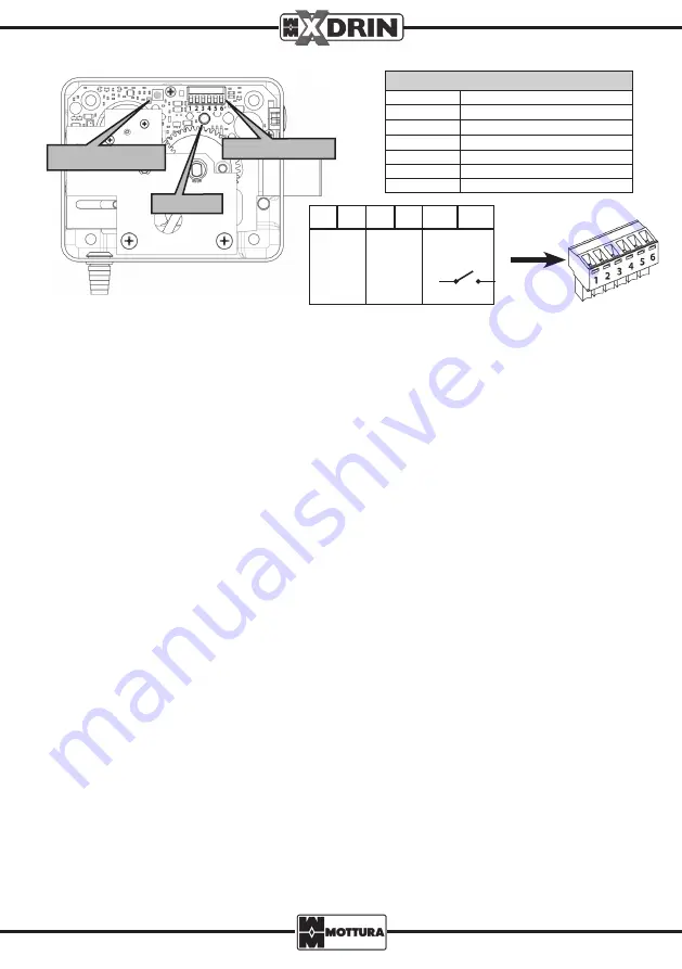
DESCRIPTION OF TERMINAL BLOCK PINS
Contact° No.
Function
1
Lock power supply
2
Lock power supply
3
Wet contact command 1
4
Wet contact command 2
5
Dry contact command (GND)
6
Dry contact command
WIRING DIAGRAMS
N.B.: All connections must be performed by trained technicians in conformance with current electrical safety stan-
dards and following good practice procedures.
The lock must be powered with a 12V or 24V DC or AC current (Pin 1 and 2, no set polarity). Commands can be issued using 12V
or 24V DC or AC impulses through wet (powered) contacts (Pin 3 and 4) or dry (volt-free) contacts (Pin 5 and 6, no set polarity).
N.B.: XDRIN does not support voltages lower than 12V and greater than 24V. To power the lock, the use of Mottura
Network Adapter (code 99.683) is recommended. Otherwise, your power supply device must necessarily bear
the CE marking and conform to the technical specifications listed in our catalogue.
XDRIN supports the simultaneous use of commands of different types (e.g., dry-contact and voltage impulse) in the
same lock. It is possible, for example, to install two buttons used, respectively, as dry contact and voltage impulse.
N.B.: Wires used for connecting the lock must be of a minimum section of 0.5mm2 and must be sheathed.
BUTTON A
LED
TERMINAL
REGULATING THE GRACE PERIOD
The grace period is the amount of time within which the door must be opened, measured from the moment the button
has been pressed. If the door has not been opened within the set grace period, it shall be locked automatically.
The default grace period is 10 seconds, but it may be changed from 5 to 60 seconds at 5-second increments. Grace
period modification procedure must be performed while the door is open and lock is unlocked, according to the
following procedure (see the components description chapter):
1. Remove the lock cover to access the internal electronic circuits;
2. Enter the programming mode by pressing the circuit button A for 3 seconds until the RED LED comes on, then release
the button;
3. The GREEN LED stays lit for 1 second and the counting starts;
4. The RED LED starts flashing. Each flash indicates a 5-second increment (e.g., 3 flashes = 15 seconds), up to a maximum
of 12 flashes (= 60 seconds);
5. Once the desired time has been reached, immediately press the button to confirm the new setting;
6. The RED-GREEN alternating flash confirms that programming has been completed successfully. Exiting the program-
ming mode is automatic.
N.B.: If the system does not detect that the button has been pressed by the user during the counting (12 flashes),
the procedure automatically restarts from step 3. If the button is not pressed again for another two cycles, the
system exits the programming mode automatically.
1
2
3
4
5
6
POWER
SUPPLY
12 - 24V
UNLOCK
IMPULSE
DRY
CONTACT


