


Mx350_01a_oi_e.docx / Nov-19
page 40 / 72
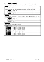
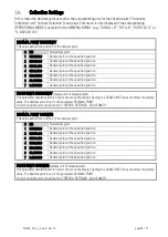
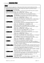
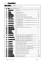
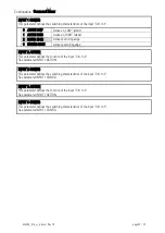
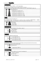
Continuation „PRESELECTION 1 MENU“:
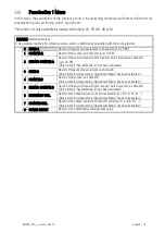
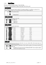
MODE 1
Switching conditions for preselection 1. Output/ relay/ display switches under the following conditions:
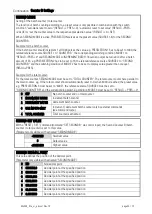
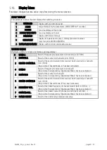
0 |RESULT|>=|PRES|
Absolute value of the display value is greater or equal absolute value of
PRESELECTION 1
With HYSTERESIS 1 not equal 0 the following switching condition is applied:
Display value >= PRESELECTION 1
ON,
Display value < PRESELECTION 1 – HYSTERESIS 1
OFF
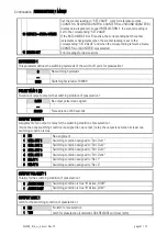
1 |RESULT|<=|PRES|
Absolute value of the display value is less or equal absolute value of
PRESELECTION 1 (start-up suppression (START UP DELAY) is advisable)
With HYSTERESIS 1 not equal 0 the following switching condition is applied:
Display value <= PRESELECTION 1
ON,
Display value > PRESELECTION 1 + HYSTERESIS 1
OFF
2 |RESULT|=|PRES|
Absolute value of the display value is equal absolute value of PRESELECTION 1
A range (Presel/- ½ Hysteresis) can be defined and monitored in
conjunction with the hysteresis.
With HYSTERESIS 1 not equal 0 the following switching condition is applied:
Display value > PRESELECTION 1 + ½ HYSTERESIS 1
OFF,
Display value < PRESELECTION 1 - ½ HYSTERESIS 1
OFF
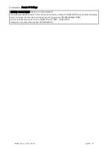
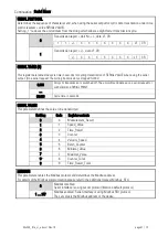
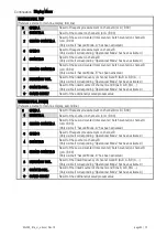
3 RESULT>=PRES
Display value is greater or equal PRESELECTION 1, e.g. overspeed
With HYSTERESIS 1 not equal 0 the following switching condition is applied:
Display value >= PRESELECTION 1
ON,
Display value < PRESELECTION 1 – HYSTERESIS 1
OFF
4 RESULT<=PRES
Display value is less or equal PRESELECTION 1, e.g. underspeed
(start-up suppression “START UP DELAY” is recommend)
With HYSTERESIS 1 not equal 0 the following switching condition is applied:
Display value <= PRESELECTION 1
ON,
Display value > PRESELECTION 1 + HYSTERESIS 1
OFF
5 RESULT=PRES
Display value is equal PRESELECTION 1. A range (Presel/- ½ Hysteresis)
can be defined and monitored in conjunction with the hysteresis.
With HYSTERESIS 1 not equal 0 the following switching condition is applied:
Display value > PRESELECTION 1 + ½ HYSTERESIS 1
OFF,
Display value < PRESELECTION 1 - ½ HYSTERESIS 1
OFF
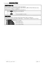
6 RESULT=0
Display value is zero (Standstill after STANDSTILL TIME(s)),
e. g. standstill monitoring (only for reference source SPEED A and SPEED B).
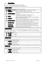
7 RESULT>= PRES->0
Auto reset to zero: (only for reference sources: COUNTER A, SECOND COUNTER A,
COUNTER B and SECOND COUNTER B)
Display value is greater or equal PRESELECTION 1, the display value is set to zero.
If the BATCH MODE A or B is active, the corresponding batch counter increments
or decrements when the display value is set to zero and when the corresponding
reference source COUNTER A or COUNTER B was selected.
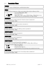
8 RESULT<= 0->SET
Auto set to PRESELECTION 1: (only for reference sources: COUNTER A, SECOND
COUNTER A, COUNTER B and SECOND COUNTER B)
Display value is less or equal zero, the display value is set to PRESELECTION 1.
If the BATCH MODE A or B is active, the corresponding batch counter increments
or decrements when PRESELECTION 1 is set and when the corresponding
reference source COUNTER A or COUNTER B was selected.
9 RES>=PRES-TRAIL
Trailing
PRESELECTION 1:
Display value is greater or equal PRESELECTION 2 – PRESELECTION 1
ON,
PRESELECTION 1 is the trailing value from PRESELECTION 2


