Motorola Solutions RFS7000GR Series RF Switch Secure Installation Guide
18
4.6 Verifying the Installation
View the LEDs on the front panel of the RFS7000 RF Switch to ensure the device is functioning
properly. The normal LED pattern follows this path:
•
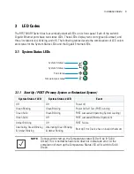
During the Power On Self Test (POST), the System 1 and System 2 LEDs both blink green.
•
If the POST test fails, the System 1 LED will blink amber. If the POST test succeeds, the System
1 LED will be lit solid green.
•
As the software is initialized, the System 2 LED will blink green.
•
After the software has finished initializing, the System 1 LED will be lit solid green and the
bottom System 2 LED will be off.
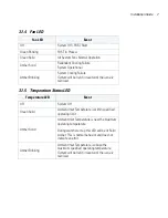
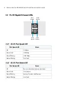
Other LED codes indicate the presence (or absence) of different standby states, or errors. A guide to
the RFS7000 Series RF Switch LEDs codes is provided in
LED Codes on page -5
.
Содержание RFS7000GR
Страница 1: ...Motorola Solutions RFS7000GR Series RF Switch FIPS Installation Guide M ...
Страница 2: ......
Страница 19: ...Installation Guide 15 4 Insert the fiber optic cables into the installed transceivers ...
Страница 58: ...Motorola Solutions RFS7000GR Series RF Switch Secure Installation Guide 54 ...

