213
16.1.2 Encryption Mode and Key
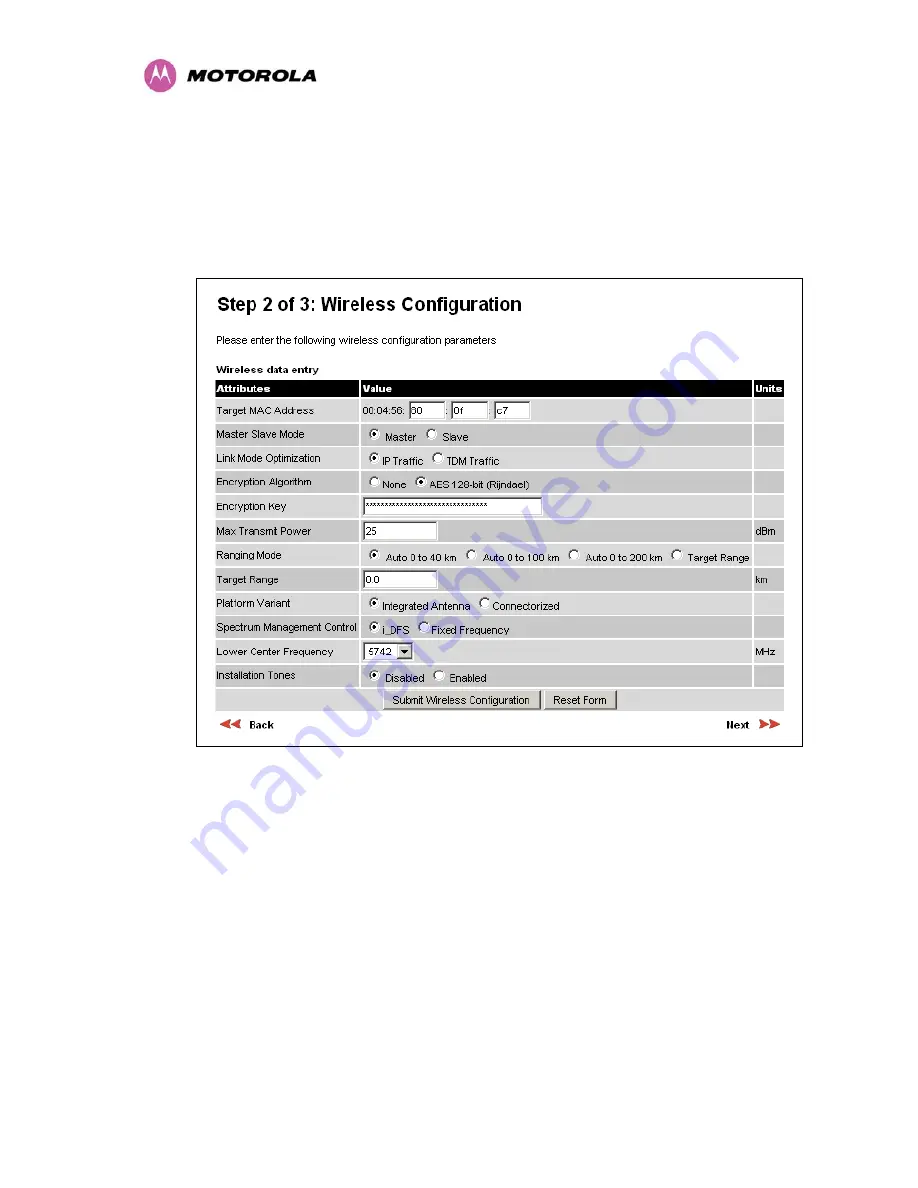
Entering the license keys only does not initialize AES link encryption. Link encryption can only
be enabled via the Configuration or Installation Wizard pages. Motorola recommends that the
Configuration page Figure 135 be used to configure AES link encryption.
Figure 135 – AES Configuration Data Entry Page
Motorola recommends the following process for entering AES link encryption configuration:-
1. Open two browsers, one for each end of the link
2. Navigate to the ‘Configuration’ data entry page for each end of the link
3. At both ends of the link select the ‘AES (Rijndael)’ Encryption Algorithm required.
4. At both ends of the link enter ether an 128-bit or 256-bit encryption key. Note the key
consists of 32/64 case insensitive hexadecimal characters. The same Key must be
entered at both ends of the link. Failure to enter the same key will cause the link to fail.
5. Submit configuration on both ends of the link, but do not reboot.
Содержание MotoWI4 PTP 600 Series
Страница 1: ...PTP 600 Series User Guide MOTOROLA POINT TO POINT WIRELESS SOLUTIONS ...
Страница 2: ......
Страница 20: ...18 ...
Страница 87: ...85 Figure 34 VLAN Configuration Fields ...
Страница 90: ...88 Figure 37 Save Configuration File Screen ...
Страница 99: ...97 8 3 3 Detailed Counters Page Figure 43 Detailed Counters Page ...
Страница 110: ...108 Figure 49 Fixed Frequency Operation ...
Страница 113: ...111 8 3 4 5 Disarm Step 5 of the installation wizard is the disarm phase Figure 52 Disarm Installation ...
Страница 165: ...163 Figure 97 Lower Grounding Configuration ...
Страница 167: ...165 Figure 98 Surge Arrestor ALPU ORT Connection Illustration Note Cable screens have been sleeved ...
Страница 180: ...178 Figure 105 Connectorized 600 Series bridge Disarm Installation Page ...
Страница 199: ...197 Figure 116 Diagrammatically Showing the E1 T1 Connections ...
Страница 201: ...199 Figure 117 Typical Mast Installation with the addition of the E1 T1 cable ...
Страница 204: ...202 Figure 119 Surge Arrestor ALPU ORT Connection Illustration ...
Страница 208: ...206 Figure 123 QPSK 0 87 Single Paylaod Figure 124 16 QAM 0 63 Single Payload Figure 125 16 QAM 0 87 Single Paylaod ...
Страница 209: ...207 Figure 126 64 QAM 0 75 Single Payload Figure 127 64 QAM 0 92 Single Payload Figure 128 256 QAM 0 81 Single Payload ...
Страница 210: ...208 Figure 129 16 QAM 0 63 Dual Payload Figure 130 16 QAM 0 87 Dual Payload Figure 131 64 QAM 0 75 Dual Payload ...
Страница 211: ...209 Figure 132 64 QAM 0 92 Dual Payload Figure 133 256 QAM 0 81 Dual Payload ...


