Installation
79
Connectors
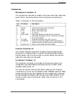
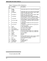
Microphone Connector J1
The microphone connector is located on the lower part of the radio front
panel. Table 1 lists the functions of the microphone connector pins.
Table 1. Connector J1, Pin Connections
Pin
No.
Pin Name
Description
1
SWA+
Line used to power up the microphone
2
RXD
Serial communication line
3
TXD
Serial communication line
4
GND
Ground line
5
MIC AUDIO
Input audio signals generated by the microphone
(600 Ohms impedance, 100 mV 1 KHz tone is required
for full output power).
6
PTT MIC
Activates transmission by short to ground.
7
MONITOR
Line which mutes the speaker before transmission is
enabled (short momentary to ground to open speaker).
8
AUDIO OUT
Receive audio 600 Ohms (300 mVRMS)
Antenna Connector J2
The “N type” antenna connector is located on the rear panel of the
transceiver. In transmit mode, it is used to feed the antenna with the
transmit power; and in receive mode it is used to deliver the received
signal from the antenna to the radio.
Accessory Connector J3
The accessory connector J3 is located on the radio rear panel. It is
intended for use with external accessories such as: modem, linear
amplifier, phone patch, etc.
The user can use the 25-pin D-type plug to make his own required
connections or he can use the Interface cable FKN4403 (same as S809
option) when Morse key and headphones are needed to be connected
by their standard connectors. Also, the user can utilize FLN2271 if he
needs to connect up to four devices. Table 2 lists Connector J3, Pin
Connections.
Содержание MICOM-2E ALE
Страница 1: ...MICOM 2E ALE HF SSB Transceiver 68P02952C60 O Owner s Guide ...
Страница 3: ......
Страница 5: ......
Страница 17: ...MICOM 2E ALE Owner s Manual xii blank ...
Страница 23: ...MICOM 2E ALE Owner s Manual xviii blank ...
Страница 33: ...MICOM 2E ALE Owner s Manual 10 blank ...
Страница 51: ...MICOM 2E ALE Owner s Manual 28 blank ...
Страница 80: ......
Страница 100: ...Automatic Link Establishment ALE 61 8 Press any key to establish the link 9 Press to disconnect the call ...
Страница 114: ...Installation 75 Figure 9 Wire Attachment to Chassis ...
Страница 129: ...90 Toggling the speaker setting 65 Transmitting 26 Turning the radio on 11 ...
Страница 132: ...68P02952C60 O 68O2952C60 ...

