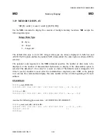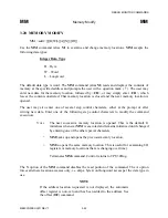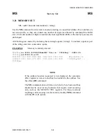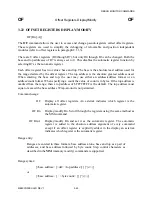
DEBUG MONITOR COMMANDS
M68CPU32BUG/D REV 1
3-54
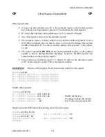
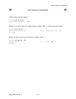
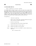
RD
Register Display
RD
EXAMPLES
CPU32Bug>rd<CR>
PC
=00003000
SR
=2700=TR:OFF_S_7_.....
VBR
=00000000
SFC
=0=F0
DFC
=0=F0
USP
=0000F830
SSP*
=00004000
D0
=00000000
D1
=00000000
D2
=00000000
D3
=00000000
D4
=00000000
D5
=00000000
D6
=00000000
D7
=00000000
A0
=00000000
A1
=00000000
A2
=00000000
A3
=00000000
A4
=00000000
A5
=00000000
A6
=00000000
A7
=00004000
00003000
424F
DC.W
$424F
CPU32Bug>
NOTES
An asterisk following a stack pointer name indicates an active
stack pointer. To facilitate reading the status register it includes a
mnemonic portion. These mnemonics are:
Trace Bits
The trace bits (T0, T1) control the trace feature of the MCU and are
displayed by the mnemonic as shown in the following table. The user
should not modify these bits when executing user programs.
T1
T0
Mnemonic
Description
0
0
TR:OFF
Trace off
0
1
TR:CHG
Trace on change of flow
1
0
TR:ALL
Trace all states
1
1
TR:INV
Invalid mode
S Bits
The bit name (S) appears if the supervisor/user state bit is set, otherwise a
period (.) indicates it is cleared.
Interrupt Mask
A number from 0 to 7 indicates the current processor priority level.
Condition Codes
The bit name (X, N, Z, V, C) appears if the respective bit is set, otherwise
a period (.) indicates it is cleared.
Содержание M68CPU32BUG
Страница 16: ...GENERAL INFORMATION M68CPU32BUG D REV 1 1 8 ...
Страница 30: ...DEBUG MONITOR DESCRIPTION M68CPU32BUG D REV 1 2 14 ...
Страница 102: ...DEBUG MONITOR COMMANDS M68CPU32BUG D REV 1 3 72 ...
Страница 168: ...DIAGNOSTIC FIRMWARE GUIDE M68CPU32BUG D REV 1 6 24 ...

