background image

Mesh Enabled Architecture  


EWR/PWR Users Guide 

3.3.2


Statically Provisioned Scheme ................................................................................... 21


3.3.3


User Supplied Scheme............................................................................................... 22


3.3.3.1


Setting User Supplied IP Addresses .......................................................... 22


3.4


External Device Provisioning.................................................................................24


3.4.1


Connecting to the Ethernet Port ................................................................................. 25


4


DEVICE MAINTENANCE ...................................................................................... 26


4.1


Resetting the EWR via the Device Administration Web Page.............................26


4.2


Restoring Factory Settings – User Supplied Mode Limitations..........................28


4.2.1


Recovering from EWR/PWR Reset-to-Default in User-Supplied Mode ..................... 28


4.2.1.1


Resetting Device Addressing Mode Using Device Manager ..................... 28


4.2.1.2


Resetting Device Addressing Mode via Configuration Web Page............. 28


4.2.1.3


Resetting User-Supplied Parameters via Configuration Web Page .......... 28


4.3


Restoring Factory Settings – Normal Operations ................................................29


4.4


Changing the Web Interface Password.................................................................31


4.5


Security Provisioning Web Page ...........................................................................33


4.5.1


Provision Username Section ...................................................................................... 33


4.5.2


Provision Groupname Section.................................................................................... 33


4.6


Upgrading the Device Firmware ............................................................................34


5


CUSTOMER SERVICE INFORMATION................................................................ 36


5.1


Obtaining Support...................................................................................................36


5.2


System Information.................................................................................................36


5.3


Return Material Request .........................................................................................37


5.4


Radio Products and Services Division..................................................................37


5.4.1


Radio Products and Services Division Telephone Numbers...................................... 37


5.5


Returning System Components to Motorola ........................................................37


5.6


Returning FREs .......................................................................................................37


6


WARRANTY INFORMATION ................................................................................ 38


7


FCC REGULATORY INFORMATION ................................................................... 41


7.1


FCC Information ......................................................................................................41


7.2


FCC RF Radiation Exposure Statement ................................................................41


8


SAFETY INFORMATION FOR THE MEA PRODUCTS ........................................ 42


9


SAFETY CERTIFICATION .................................................................................... 43


9.1


CE Mark Certification ..............................................................................................43


Содержание EWR6300

Страница 1: ...MEA Enhanced Wireless and Portable Wireless Routers Users Guide Documentation Revision 3 1 2 ...

Страница 2: ......

Страница 3: ... normal nonexclusive royalty free license to use that arises by operation of law in the sale of a product Disclaimer Please note that certain features facilities and capabilities described in this document may not be applicable to or licensed for use on a particular system or may be dependent upon the characteristics of a particular mobile subscriber unit or configuration of certain parameters Ple...

Страница 4: ...300 Assembly Information 10 2 6 1 PWR Installation Procedure 11 2 7 Device Deployment Considerations 11 2 7 1 Antenna Deployment Tips 12 2 8 Testing the Device Installation 12 3 DEVICE CONFIGURATION 13 3 1 IP Addressing Considerations 13 3 2 Accessing the MEA Device Administration Web Pages 13 3 2 1 User Name and Administrator Access Information 13 3 2 2 Viewing MEA Redirecting Page 15 3 2 3 Viewi...

Страница 5: ...ng User Supplied Parameters via Configuration Web Page 28 4 3 Restoring Factory Settings Normal Operations 29 4 4 Changing the Web Interface Password 31 4 5 Security Provisioning Web Page 33 4 5 1 Provision Username Section 33 4 5 2 Provision Groupname Section 33 4 6 Upgrading the Device Firmware 34 5 CUSTOMER SERVICE INFORMATION 36 5 1 Obtaining Support 36 5 2 System Information 36 5 3 Return Mat...

Страница 6: ...vi ...
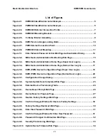
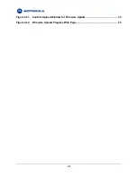
Страница 7: ... 3 4 MEA Device Administration Home Page Normal User Login 17 Figure 3 5 EWR PWR Device Configuration Page Super User Login 18 Figure 3 6 EWR PWR Device Configuration Page Normal User Login 20 Figure 3 7 Configuration Change Dialog 22 Figure 3 8 System Update Save Completed Web Page 23 Figure 3 9 External Device Provisioning Table 24 Figure 4 1 Device Reset Prompt Web Page 26 Figure 4 2 Device Res...

Страница 8: ...Figure 4 11 Confirm Upload Window for Firmware Update 35 Figure 4 12 Firmware Upload Progress Web Page 35 viii ...

Страница 9: ...tive wireless network component This makes it easy for any Ethernet ready device to access a Mesh Enabled Architecture MEA mobile broadband network IP enabled computers video cameras sensors signs signals and other devices can all be Mesh Enabled to send and receive data at burst rates of up to 6 Mbps All standard Wireless Router functionality including Multi Hopping near Line of Sight communicati...

Страница 10: ...ss broadband network without the need to purchase a separate Wireless Modem Card The MEA Portable Wireless Router 6300 PWR6300 is an infrastructure device positioned in a fixed location such as on a traffic cabinet or outdoor kiosk The PWR6300 provides range extension a means to route around obstructions a fixed location reference for use in Geo Location and the capability of enabling IP devices 2...

Страница 11: ...nnector Mounting Bracket The Network Operator must supply the following Mounting Location Power Source 120V A C or 5 V D C depending on EWR configuration Hand tools for bracket installation 7 16 wrench 2 Phillips screwdriver Optional Equipment DC powered EWR EWR6300 DC IN Power cord to connect to a photoelectric cell Optional FCC Approved Antennas Manufacturer Part Number Gain Usage Maxrad MFB2400...

Страница 12: ...g Location Power Source 12 VDC Hand tools for bracket installation Optional Equipment An Antenna Cable and connector Antenna Options are the following Manufacturer Part Number Gain Usage Maxrad BMMG2400ML195MSMA 0 dBi Mobile Antenex TRA24003 3 dBi Mobile 4 ...

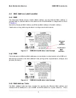
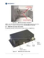
Страница 13: ...ed later to configure and test the device Figure 2 1 EWR6300 Identification Label Example Transceiver MAC Address Ethernet MAC Address 2 4 2 PWR The transceiver and Ethernet MAC addresses are recorded on a label located on the PWR unit Record these numbers in the MAC Address Table as they will be required later to configure and provision the device Figure 2 2 PWR6300 Identification Label Example 2...

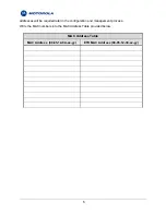
Страница 14: ...ill be required later in the configuration and management process Write the MAC numbers into the MAC Address Table provided below MAC Address Table MAC Address 00 05 12 0A xx yy ETH MAC Address 00 05 12 30 xx yy 6 ...

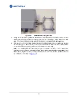
Страница 15: ...ion 2 4 3 Both addresses will be required to configure and test the device 5 The Test Port is unused during deployment 2 5 3 EWR6300 Mounting Bracket The EWR6300 mounting bracket is identical to the mounting bracket for the IAP6300 and the MWR6300 The bracket is robust secure and can be used for horizontal vertical and off angle pole mounted installations The mounting bracket is preinstalled and s...

Страница 16: ... Clamp Bracket bolts so that the bracket can be positioned around the mounting pole If necessary remove the second bolt When the two halves of the Clamp Bracket are correctly positioned reinstall the bracket bolts Note The C Clamp Bracket Assembly requires two 3 1 2 x 1 4 inch stainless steel bolts to secure the C Clamp to a mounting pole Each bolt is supplied with 2 stainless steel flat washers 1...

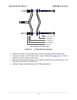
Страница 17: ...ion the bracket in the desired location and securely tighten the two bracket bolts 4 If required loosen the Pivot Bolt and the Angle Locking Bolt Figure 2 6 so that the antenna connector is positioned vertically 5 Ensure that the antenna connector is still vertical and tighten the Pivot Bolt using a 7 16 inch open end wrench or socket wrench 6 Tighten the Angle Locking Bolt using a 1 Phillips scre...

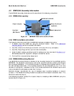
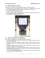
Страница 18: ...sures may have a bolt or plug in the center of the back of the box To maintain the integrity of the box DO NOT REMOVE THIS PLUG 2 6 PWR6300 Assembly Information The VMM6300 Assembly shows the external connection points on a VMM6300 box N Type Antenna Connector Power Reset Power Connector Ethernet Crossover MDI X Figure 2 7 PWR External Connection Point 10 ...

Страница 19: ...ment Considerations When deploying the EWR6300 or the PWR6300 consider the following The antenna should be a minimum of 30 inches from any nearby metal poles to avoid distortion of the RF pattern The antenna must have a separation distance of at least 2 meters from the body of all persons and must not be co located or operating in conjunction with any other antenna or transmitter Users and install...

Страница 20: ...this document The address will be in the format 00 05 12 0A xx yy for the transceiver and 00 05 12 30 xx yy for Ethernet 3 From the MeshManager software screen display the devices using the Display MAC Addresses selection from the Preferences menu Note This step assumes that the device has been automatically detected via the Auto Add feature or manually added using the Add New Device menu item in ...

Страница 21: ...onfiguration for the EWR PWR using the web interface you must know the IP address assigned to the EWR PWR SBC The mechanism for assigning the IP address is controlled by the addressing mode of the EWR PWR SBC Regardless of the mechanism the assigned IP address can always be displayed using MeshManager If the factory setting is used then the default addressing mode will be Remote DHCP and the EWR P...

Страница 22: ...age may be provisioned via MeshManager instead The password for the admin account should be changed during installation The Access or Normal User account password can be changed by the Administrator NOTE If you are running a EWR PWR as a standalone device the configuration web page can be reached by connecting a PC to the wired interface Figure 3 1 Enter Network Password Initial Web Page Authentic...

Страница 23: ...recting Page After the login authentication has been completed the web browser will display a redirecting page and your browser will automatically transition to the home web page for MEA Device Administration Figure 3 2 MEA Device Administration Redirecting Web Page 15 ...

Страница 24: ...d management security provisioning firmware upgrades device reset and restoring the factory default configuration Figure 3 3 MEA Device Administration Home Page Super User Login 3 2 3 1 Viewing MEA Device Administration Home Page as a Normal User When logging in with the Access Account or Normal User the MEA Device Administration home page provides basic information about the device including the ...

Страница 25: ...Mesh Enabled Architecture EWR PWR Users Guide Figure 3 4 MEA Device Administration Home Page Normal User Login 17 ...

Страница 26: ... Administrator role the EWR Device Administration Super User Login Configuration page allows for changes to the configuration of EWR and PWR devices Figure 3 5 EWR PWR Device Configuration Page Super User Login The fields displayed on this page are described in the following table 18 ...

Страница 27: ... to the attached Ethernet devices 300 Device Priority The Device Priority provisioning area allows the operator to set the priority assigned to wireless messages transmitted by this device A priority of 7 is the highest priority setting Levels 0 7 are available based on your configuration as set by the Network Administrator Geo Settings The Geo Settings area allows the operator to enable and disab...

Страница 28: ...ion provided in the Geo Reference section can be used for gathering other Subscriber Device geo location information when used in conjunction with the Mesh Positioning Application software For additional information about geo location and the Mesh Positioning Application software please refer to the Mesh Positioning Application Users Guide Figure 3 6 EWR PWR Device Configuration Page Normal User L...

Страница 29: ...granted the address will be valid out of network coverage for the remainder of the lease or if a static lease was granted until the next power cycle If the lease expires or the user cycles power while outside of network coverage the user will again lose the ability to communicate with the wireless network This scheme is best for a larger closely managed network of subscribers who don t need to com...

Страница 30: ...ser Supplied radio button must be selected At that point the user may enter an IP address and subnet mask consistent with the existing network The user should also enter the IP address of the default gateway and DNS server as well as enter the domain name Note that this configures the user supplied address for the EWR PWR device To configure addresses for Ethernet clients please refer to the descr...

Страница 31: ...re 3 8 System Update Save Completed Web Page After the settings have been saved click the Finished button The web browser should return to the MEA Device Administration home page A reboot of the device is not required for the changes to take effect 23 ...

Страница 32: ... Device Provisioning Table The Enable checkbox indicates this row contains a valid address Any address can be disabled by clearing the checkbox The pull down menu options indicate whether this address will be offered via the Local DHCP or Statically Provisioned The Statically Provisioned setting is used to support devices that do not use DHCP to acquire an address The MAC address field is used for...

Страница 33: ...ill proxy and advertise The same address will be accessed by the Device Manager when using MeshManager The wired interface address will be used by the EWR PWR as the gateway address for the local Ethernet segment The wired subnet mask is configurable so that the user may select a more restrictive subnet on the local Ethernet segment than what is normally provided to the wireless subscribers The MA...

Страница 34: ...o reset the device return to the MEA Device Administration home page and click on the Reset the Device link in the Device Management panel The web page displayed will allow you to reset the device Figure 4 1 Device Reset Prompt Web Page Once you have commanded the device to reset the following screen will be displayed Your browser will delay for a short time then transition to the home page once m...

Страница 35: ...led Architecture EWR PWR Users Guide Figure 4 2 Device Reset in Progress Page NOTE After the completion of the reset you may experience a significant delay when bringing up another web page Please be patient 27 ...

Страница 36: ...evice addressing mode via Device Manager to either Remote DHCP or Statically Provisioned 4 2 1 2 Resetting Device Addressing Mode via Configuration Web Page Because the factory default settings were restored the EWR PWR will offer one IP address via DHCP This address will be in the form 10 xx yy 10 where xx and yy are based on the transceiver MAC address as described in the EWR PWR User s Manual T...

Страница 37: ... the following web page Figure 4 3 Restore Factory Settings Web Page The Restore Factory Defaults function allows the operator to return the device to factory defaults This change will include the web password for the administrator and access accounts This will also return the local IP addresses to the default MAC derived values The confirmation window will be displayed Click on the OK button to c...

Страница 38: ...onfirm Changes Window for Restore Factory Settings The Factory Settings Restored page will be displayed Figure 4 5 Factory Settings Restored Web Page Click on the Finished button to complete the reset procedure 30 ...

Страница 39: ...tor or the Change User Password function is selected the device will present the following web page Figure 4 6 Enter New Password Web Page The operator is expected to enter a new password for the web account and click on the Submit button Once the password entry is complete the device will prompt the operator for confirmation of the change Figure 4 7 Confirm Changes Window for Enter New Password 3...

Страница 40: ... operator confirms the change the new password will be stored in flash and the device will present a status screen indicating that the change was successful Figure 4 8 Password Changed Confirmation Web Page 32 ...

Страница 41: ...ed in this field is used to communicate to the IAP and can be changed from this screen If a new username is entered the previous username will not be retained Password and Re enter new password These two fields can be used to change the password for an existing username or to provide a password for a new username 4 5 2 Provision Groupname Section Groupname the group name provided in this field is ...

Страница 42: ...le from a released upgrade package When the Upgrade Device Firmware function is selected from the MEA Device Administration Home Page the device will present the following web page Figure 4 10 Update Device Firmware Web Page This page allows entry of the name and path of the upgrade file Once the correct filename has been entered the device will prompt for confirmation 34 ...

Страница 43: ...eb browser will transmit the file to the device and the device will present an upgrade progress screen This page will indicate the current stage in the upgrade process Figure 4 12 Firmware Upload Progress Web Page Once the upgrade is completed the device must be reset The Finished button will transition the web browser to the reset screen 35 ...

Страница 44: ...eck your contract for specific warranty and service information 5 2 System Information To be provided with the best possible opportunity for support collect the following system information and have it available when obtaining support Location of the system Date the system was put into service Software or firmware version information for components of your system Serial number s of the device s or...

Страница 45: ...rvice philosophy is based on field replaceable entities FREs FREs are system components identified by Motorola to be returned to Motorola for repair In turn Motorola sends you a replacement FRE component to help you maintain maximum operating performance for your system 5 6 Returning FREs Return faulty FREs to Motorola for repair When you return an assembly for service follow these best practices ...

Страница 46: ...or modifications to this warranty unless made in writing and signed by an officer of Motorola Unless made in a separate written agreement between Motorola and the original end user purchaser Motorola does not warrant the installation maintenance or service of the Product Motorola cannot be responsible in any way for any ancillary equipment not furnished by Motorola which is attached to or used in ...

Страница 47: ...f the Motorola supplied products from light power telephone poles etc O Dispatch to remote site locations P Loading of software upgrades or fixes into the devices V GOVERNING LAW In the case of a Product sold in the United States and Canada this Warranty is governed by the laws of the State of Illinois and the Province of Ontario respectively VI PATENT AND SOFTWARE PROVISIONS Motorola will defend ...

Страница 48: ...eproduce in copies and distribute copies of such Motorola software Motorola software may be used in only the Product in which the software was originally embodied and such software in such Product may not be replaced copied distributed modified in any way or used to produce any derivative thereof No other use including without limitation alteration modification reproduction distribution or reverse...

Страница 49: ...nst harmful interference in a commercial installation This equipment generates uses and can radiate radio frequency energy and if not installed and used in accordance with the instructions may cause harmful interference to radio communications However there is no guarantee that interference will not occur in a particular installation If this equipment does cause harmful interference to radio or te...

Страница 50: ... the FCC recommended limits Do not touch or move the antenna s while the unit is transmitting or receiving Do not hold any component containing a radio such that the antenna is very close to or touching any exposed parts of the body especially the face or eyes while transmitting Do not operate a portable transmitter near unshielded blasting caps or in an explosive environment unless it is a type e...

Страница 51: ...afety and environmental requirements as they are defined in the European Directives Motorola Products are covered under the following product certification Europe ETSI EN 300 328 V 141 2003 04 ETSI EN 301 489 1 2002 08 and 301 489 17 EN 55022 1998 and EN 55024 1998 CENELEC EN 50360 and EN50371 Specific Absorption Test SAR The following countries are covered under the CE Mark Austria Belgium Demark...

Страница 52: ...Alert Symbol CE Mark The alert symbol indicates that Motorola products are not certified to operate in France Outdoor use in France is restricted to 10mW EIRP for band 2454 2483 5 MHz 44 ...

Отзывы: