Theory of Operation
: Controller
3-67
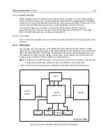
3.2.8.5 Key Zeroize
The encryption keys can also be manually erased by holding down the monitor and emergency
buttons during radio power-up. These two button inputs both connect to a dual transistor Q5001,
which will release the Key_ZEROIZE signal sensed by MACE's TPRO (U5003-M2). Once this
condition is sensed (floating high), the encryption keys will be erased.
To troubleshoot the encryption circuitry, refer to the flowcharts in
Chapter 5 “Troubleshooting Charts”
.
3.2.9
Bluetooth Module Interface
A 60-pin connector (J3001) contains various interfaces from the Vocon Board that are made
available to the Bluetooth Option Board.
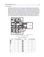
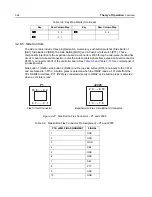
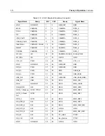
Table 3-15
shows the various groups of interfaces available at J3001. The interface groups are
described in the next section.
3.2.9.1 Bluetooth Option Board Signal Groups
From
Table 3-15
, the Bluetooth Interface is divided into 10 signal groups: Power, Ground (GND),
One-Wire, GPIO, Camera, I2C, SDIO, SSI, USB, and Type 1/GPIO.
3.2.9.2 Power / Ground
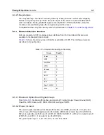
The power supplies available at the Bluetooth Interface are , SW_B+, VCC_2.8, and
VCC_1.8 (see DC Power Supplies section for details). is routed to pin 30 (J3001-30),
SW_B+ is routed to pins 27,29, and 31 (J3001-27, J3001-29, J3001-31), VCC_2.8 is routed to pin 23
(J3001-23), and VCC_1.8 is routed to pin 24 (J3001-24).
The ground pins are pin 1, 2, 25, 26, 28, 34, 37, and 59 at J3001.
Table 3-15. Bluetooth Module Signal Summary
Group
Signals
Power 6
GND
8
One Wire
1
GPIO
5
Camera
17
I2C
2
SDIO
9
SSI
6
USB
3
Type 1 / GPIO
3
Total
60
Содержание ASTRO APX 7000
Страница 1: ......
Страница 4: ...iv Document History Notes ...
Страница 24: ...2 4 Radio Power DC Power Routing VOCON Board Notes ...
Страница 98: ...3 74 Theory of Operation Global Positioning System GPS ...
Страница 104: ...4 6 Troubleshooting Procedures Power Up Self Check Diagnostics and Repair Not for Field Use Notes ...
Страница 163: ...Troubleshooting Charts PA Failure 5 59 ...
Страница 164: ...5 60 Troubleshooting Charts PA Failure ...
Страница 168: ...6 4 Troubleshooting Waveforms Clocks 6 2 2 4 MHz Clock Trace 1 Trace recorded at R6113 Figure 6 2 4 MHz Clock Waveform ...
Страница 174: ...6 10 Troubleshooting Waveforms Audio SSI 6 3 3 Sync Trace 1 Trace recorded at R3005 Figure 6 8 Audio SSI Sync Waveform ...
Страница 175: ...Troubleshooting Waveforms Audio SSI 6 11 6 3 4 BCLK Trace 1 Trace recorded at R3006 Figure 6 9 Audio SSI BCLK Waveform ...
Страница 177: ...Troubleshooting Waveforms RX SSI 6 13 6 4 2 DA Trace 1 Trace recorded at R1005 Figure 6 11 RX SSI DA Waveform ...
Страница 178: ...6 14 Troubleshooting Waveforms RX SSI 6 4 3 FSync Trace 1 Trace recorded at R1004 Figure 6 12 RX SSI FSync Waveform ...
Страница 180: ...6 16 Troubleshooting Waveforms TX SSI 6 5 2 DA Trace 1 Trace recorded at R1017 Figure 6 14 TX SSI DA Waveform ...
Страница 181: ...Troubleshooting Waveforms TX SSI 6 17 6 5 3 FSync Trace 1 Trace recorded at R1007 Figure 6 15 TX SSI FSync Waveform ...
Страница 182: ...6 18 Troubleshooting Waveforms SPI 6 6 SPI 6 6 1 CLK Trace 1 Trace recorded at R6605 Figure 6 16 SPI CLK Waveform ...
Страница 183: ...Troubleshooting Waveforms SPI 6 19 6 6 2 CLK INV Trace 1 Trace recorded at R2325 Figure 6 17 SPI CLK INV Waveform ...
Страница 184: ...6 20 Troubleshooting Waveforms SPI 6 6 3 CS Trace 1 Trace recorded at Pin 34 of J2301 Figure 6 18 SPI CS Waveform ...
Страница 185: ...Troubleshooting Waveforms SPI 6 21 6 6 4 MOSI Trace 1 Trace recorded at R6603 Figure 6 19 SPI MOSI Waveform ...
Страница 187: ...Troubleshooting Waveforms I2C BUS 6 23 6 7 2 SCL 5V Trace 1 Trace recorded at R6204 Figure 6 21 I2C Bus SCA 5V Waveform ...
Страница 188: ...6 24 Troubleshooting Waveforms I2C BUS 6 7 3 SDA Trace 1 Trace recorded at R6209 Figure 6 22 I2C Bus SDA Waveform ...
Страница 194: ...6 30 Troubleshooting Waveforms USB 6 10 2 D Trace 1 Trace recorded at Pin 35 of J3001 Figure 6 28 USB D Waveform ...
Страница 196: ...6 32 Troubleshooting Waveforms UART 6 11 2 TX Trace 1 Trace recorded at F_Boot_Tx Figure 6 30 UART TX Waveform ...
Страница 198: ...6 34 Troubleshooting Waveforms SDRAM 6 12 2 CLKX Trace 1 Trace recorded at TP6308 Figure 6 32 SDRAM CLKX Waveform ...
Страница 276: ...7 58 Troubleshooting Tables List of Board and IC Signals Notes ...
Страница 318: ...8 42 Schematics Boards Overlays and Parts Lists Transceiver RF Boards VHF 700 800 Notes ...
Страница 380: ...8 104 Schematics Boards Overlays and Parts Lists Transceiver RF Boards UHF1 700 800 MHz Notes ...
Страница 432: ...8 156 Schematics Boards Overlays and Parts Lists Transceiver RF Boards UHF1 VHF Notes ...
Страница 458: ...8 182 Schematics Boards Overlays and Parts Lists Transceiver RF Boards UHF1 UHF2 Notes ...
Страница 498: ...8 222 Schematics Boards Overlays and Parts Lists Transceiver RF Boards UHF2 700 800 MHz Notes ...
Страница 546: ...8 270 Schematics Boards Overlays and Parts Lists Transceiver RF Boards UHF2 VHF Notes ...
Страница 606: ...8 330 Schematics Boards Overlays and Parts Lists VOCON Boards Notes ...
Страница 638: ...Glossary 10 Glossary Notes ...
Страница 643: ......

