


Theory of Operation:
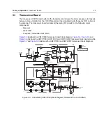
Transceiver Board
3-7
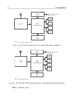
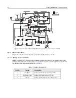
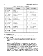
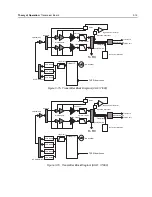
3.1.1.2 VOCON Connector J1001
VOCON connector J1001 is a 40 pin board to board connector that connects to XCVR board
connector P101. This is a digital interface carrying DC power, control, and data between the XCVR
and VOCON boards.
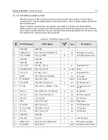
Table 3-2
lists the connector pins, their signals, and functions. SPI refers to serial peripheral
interface, which is the control bus from the microprocessor. SSI is the serial synchronous interface
bus for data to and from the DSP. There is a RX SSI bus for demodulated data from the receiver and
a TX SSI bus for modulation data to the transmitter.
Table 3-2. VOCON Connector J1001
Pin
No.
VOCON Signal
XCVR Signal
XCVR
I/O
Type
Description
1
GROUND
GROUND
–
–
–
2
EEPROM_CS
DIG_CTRL_SPI_EEPROM_PE
I
spi
SPI EEprom chip select
3
CLK_16.8MHZ
CLK_16_8MHZ
O
rf
16.8 MHz reference clock
4
GROUND
GROUND
–
–
–
5
GROUND
GROUND
–
–
–
6
VCC_1.875
DC_LIN_1_875_D
I
dc
Regulated 1.875 V
7
RF_BRD_RSTB
DIG_CTRL_RSTB
I/O
control
Reset
8
VCC_2.775
DC_LIN_2_775V
I
dc
Regulated 2.775 V
9
DMCS
DIG_CTRL_SSI_TRIGGER
I
ssi
SSI Trigger
10
F2_PARAMP
DIG_CTRL_IO49
I
control
TX Slot enable
11
RX_FSYNC
DIG_DATA_SSI_RX_FS
O
ssi
RX SSI frame sync
12
TX_INH
DIG_CTRL_TX_INHIBIT_TYPE_1
I
control
TX inhibit control for
secure
13
RX_DA
DIG _DATA _SSI _RX _DOUTA
O
ssi
RX SSI data
14
DAC_CS
DIG_CTRL_SPI_DAC_PE
I
spi
SPI DAC chip select
15
RX_CLK
CLK_SSI_RX
O
ssi
RX SSI clock
16
ISET
ANA_CTRL_ISET
I
control
Mako Ramp
17
TX_FSYNC
DIG_TX_SSI_FS
I
ssi
TX SSI frame sync
18
TX_DA_CONN
DIG_DATA_TX_SSI
I
ssi
TX SSI data
19
TX_CLK
DIG_TX_SSI_CLK
I
ssi
TX SSI clock
20
GROUND
GROUND
–
–
–
21
GPS_ANT RF_GPS
O
rf
GPS_RF
signal
22
ABACUS_CS
DIG_CTRL_SPI_ABACUS_PE
I
spi
SPI Abacus chip select
23
F2_SYNCB
DIG_SYNCB
I
control
Synchronize RX SSI data
Содержание ASTRO APX 7000
Страница 1: ......
Страница 4: ...iv Document History Notes ...
Страница 24: ...2 4 Radio Power DC Power Routing VOCON Board Notes ...
Страница 98: ...3 74 Theory of Operation Global Positioning System GPS ...
Страница 104: ...4 6 Troubleshooting Procedures Power Up Self Check Diagnostics and Repair Not for Field Use Notes ...
Страница 163: ...Troubleshooting Charts PA Failure 5 59 ...
Страница 164: ...5 60 Troubleshooting Charts PA Failure ...
Страница 168: ...6 4 Troubleshooting Waveforms Clocks 6 2 2 4 MHz Clock Trace 1 Trace recorded at R6113 Figure 6 2 4 MHz Clock Waveform ...
Страница 174: ...6 10 Troubleshooting Waveforms Audio SSI 6 3 3 Sync Trace 1 Trace recorded at R3005 Figure 6 8 Audio SSI Sync Waveform ...
Страница 175: ...Troubleshooting Waveforms Audio SSI 6 11 6 3 4 BCLK Trace 1 Trace recorded at R3006 Figure 6 9 Audio SSI BCLK Waveform ...
Страница 177: ...Troubleshooting Waveforms RX SSI 6 13 6 4 2 DA Trace 1 Trace recorded at R1005 Figure 6 11 RX SSI DA Waveform ...
Страница 178: ...6 14 Troubleshooting Waveforms RX SSI 6 4 3 FSync Trace 1 Trace recorded at R1004 Figure 6 12 RX SSI FSync Waveform ...
Страница 180: ...6 16 Troubleshooting Waveforms TX SSI 6 5 2 DA Trace 1 Trace recorded at R1017 Figure 6 14 TX SSI DA Waveform ...
Страница 181: ...Troubleshooting Waveforms TX SSI 6 17 6 5 3 FSync Trace 1 Trace recorded at R1007 Figure 6 15 TX SSI FSync Waveform ...
Страница 182: ...6 18 Troubleshooting Waveforms SPI 6 6 SPI 6 6 1 CLK Trace 1 Trace recorded at R6605 Figure 6 16 SPI CLK Waveform ...
Страница 183: ...Troubleshooting Waveforms SPI 6 19 6 6 2 CLK INV Trace 1 Trace recorded at R2325 Figure 6 17 SPI CLK INV Waveform ...
Страница 184: ...6 20 Troubleshooting Waveforms SPI 6 6 3 CS Trace 1 Trace recorded at Pin 34 of J2301 Figure 6 18 SPI CS Waveform ...
Страница 185: ...Troubleshooting Waveforms SPI 6 21 6 6 4 MOSI Trace 1 Trace recorded at R6603 Figure 6 19 SPI MOSI Waveform ...
Страница 187: ...Troubleshooting Waveforms I2C BUS 6 23 6 7 2 SCL 5V Trace 1 Trace recorded at R6204 Figure 6 21 I2C Bus SCA 5V Waveform ...
Страница 188: ...6 24 Troubleshooting Waveforms I2C BUS 6 7 3 SDA Trace 1 Trace recorded at R6209 Figure 6 22 I2C Bus SDA Waveform ...
Страница 194: ...6 30 Troubleshooting Waveforms USB 6 10 2 D Trace 1 Trace recorded at Pin 35 of J3001 Figure 6 28 USB D Waveform ...
Страница 196: ...6 32 Troubleshooting Waveforms UART 6 11 2 TX Trace 1 Trace recorded at F_Boot_Tx Figure 6 30 UART TX Waveform ...
Страница 198: ...6 34 Troubleshooting Waveforms SDRAM 6 12 2 CLKX Trace 1 Trace recorded at TP6308 Figure 6 32 SDRAM CLKX Waveform ...
Страница 276: ...7 58 Troubleshooting Tables List of Board and IC Signals Notes ...
Страница 318: ...8 42 Schematics Boards Overlays and Parts Lists Transceiver RF Boards VHF 700 800 Notes ...
Страница 380: ...8 104 Schematics Boards Overlays and Parts Lists Transceiver RF Boards UHF1 700 800 MHz Notes ...
Страница 432: ...8 156 Schematics Boards Overlays and Parts Lists Transceiver RF Boards UHF1 VHF Notes ...
Страница 458: ...8 182 Schematics Boards Overlays and Parts Lists Transceiver RF Boards UHF1 UHF2 Notes ...
Страница 498: ...8 222 Schematics Boards Overlays and Parts Lists Transceiver RF Boards UHF2 700 800 MHz Notes ...
Страница 546: ...8 270 Schematics Boards Overlays and Parts Lists Transceiver RF Boards UHF2 VHF Notes ...
Страница 606: ...8 330 Schematics Boards Overlays and Parts Lists VOCON Boards Notes ...
Страница 638: ...Glossary 10 Glossary Notes ...
Страница 643: ......