Theory of Operation:
Transceiver Board
3-13
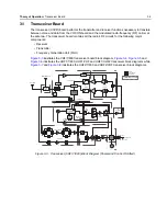
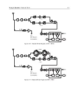
3.1.2.1 VHF Front-End
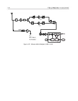
From the first band select switch, U1122, a VHF signal is routed to the first pre-selector filter followed
by a Low Noise Amplifier (LNA) and a second pre-selector filter. Both filters are discrete and fixed
designs and are used to band limit the incoming energy and suppress known spurious responses
such as Image and the ½ IF spur. The LNA active device is an NPN transistor (U302) with active bias
provided by transistor pair Q302.
The output of the second pre-selector filter is applied to the RF port of the Mixer IC via a second
band select switch, U501. The Mixer IC, U506, is driven by a Local Oscillator (LO) signal generated
by the Trident synthesizer IC, U702, at the LO port to down-convert the RF signal to a 109.65 MHz
intermediate frequency (IF). It is a passive, high linearity design with balanced inputs at the RF and
IF ports and internal LO buffer. The down converted IF signal is passed through a 3-pole crystal filter,
FL501, and an IF amplifier, Q503, which drive the input of the Analog to Digital Converter IC, U601.
3.1.2.2 700/800 Front-End
From the first band select switch, U1122, a 700 MHz or 800 MHz band signal is routed to a second
band SPST switch, U402, which selects the 700 or the 800 band signal and routes it to the
appropriate first pre-selector filter, FL401. A third band select switch, U404, selects the output of the
appropriate filter and applies it to an LNA followed by a similar pre-selector filter/ band-select switch
circuit. The signal is then routed to second LNA, U407, whose output is applied to a discrete image
filter. Both preselector filters are Surface Acoustic Wave designs (EPCOS B4232) used to band limit
the received energy and suppress known spurious responses such as Image and the ½ IF spur. The
output of the discrete image filter is applied to the RF port of the Mixer IC, U506, via a second band
select switch, U501. The Mixer IC is driven by an LO signal generated by the Trident synthesizer IC,
U702, and applied to the LO port to down-convert the RF signal to a 109.65 MHz intermediate
frequency (IF).
The IF signal is passed through a crystal filter, FL501, and an IF amplifier, Q503, which drive the
input of the Analog to Digital Converter IC, U601.
3.1.2.3 UHF1 Front-End
From the first band select switch, U1122, a UHF1 signal is routed to the first pre-selector filter
followed by a Low Noise Amplifier (LNA) and a second pre-selector filter. Both filters are discrete and
tunable designs and are used to band limit the incoming energy and suppress known spurious
responses such as Image spur. The LNA active device is an NPN transistor (U2032) with active bias
provided by transistor pair Q2022. The output of the second pre-selector filter is applied to a discrete
Low Pass Filter (LPF). The output of the LPF is applied to the RF port of the Mixer IC via a second
band select switch, U501. The Mixer IC, U506, is driven by a Local Oscillator (LO) signal generated
by the Trident synthesizer IC, U702, at the LO port to down-convert the RF signal to a 109.65 MHz
intermediate frequency (IF). It is a passive, high linearity design with balanced inputs at the RF and
IF ports and internal LO buffer. The down converted IF signal is passed through a 3-pole crystal filter,
FL501, and an IF amplifier, Q503, which drives the input of the Analog to Digital Converter IC, U601.
Содержание ASTRO APX 7000
Страница 1: ......
Страница 4: ...iv Document History Notes ...
Страница 24: ...2 4 Radio Power DC Power Routing VOCON Board Notes ...
Страница 98: ...3 74 Theory of Operation Global Positioning System GPS ...
Страница 104: ...4 6 Troubleshooting Procedures Power Up Self Check Diagnostics and Repair Not for Field Use Notes ...
Страница 163: ...Troubleshooting Charts PA Failure 5 59 ...
Страница 164: ...5 60 Troubleshooting Charts PA Failure ...
Страница 168: ...6 4 Troubleshooting Waveforms Clocks 6 2 2 4 MHz Clock Trace 1 Trace recorded at R6113 Figure 6 2 4 MHz Clock Waveform ...
Страница 174: ...6 10 Troubleshooting Waveforms Audio SSI 6 3 3 Sync Trace 1 Trace recorded at R3005 Figure 6 8 Audio SSI Sync Waveform ...
Страница 175: ...Troubleshooting Waveforms Audio SSI 6 11 6 3 4 BCLK Trace 1 Trace recorded at R3006 Figure 6 9 Audio SSI BCLK Waveform ...
Страница 177: ...Troubleshooting Waveforms RX SSI 6 13 6 4 2 DA Trace 1 Trace recorded at R1005 Figure 6 11 RX SSI DA Waveform ...
Страница 178: ...6 14 Troubleshooting Waveforms RX SSI 6 4 3 FSync Trace 1 Trace recorded at R1004 Figure 6 12 RX SSI FSync Waveform ...
Страница 180: ...6 16 Troubleshooting Waveforms TX SSI 6 5 2 DA Trace 1 Trace recorded at R1017 Figure 6 14 TX SSI DA Waveform ...
Страница 181: ...Troubleshooting Waveforms TX SSI 6 17 6 5 3 FSync Trace 1 Trace recorded at R1007 Figure 6 15 TX SSI FSync Waveform ...
Страница 182: ...6 18 Troubleshooting Waveforms SPI 6 6 SPI 6 6 1 CLK Trace 1 Trace recorded at R6605 Figure 6 16 SPI CLK Waveform ...
Страница 183: ...Troubleshooting Waveforms SPI 6 19 6 6 2 CLK INV Trace 1 Trace recorded at R2325 Figure 6 17 SPI CLK INV Waveform ...
Страница 184: ...6 20 Troubleshooting Waveforms SPI 6 6 3 CS Trace 1 Trace recorded at Pin 34 of J2301 Figure 6 18 SPI CS Waveform ...
Страница 185: ...Troubleshooting Waveforms SPI 6 21 6 6 4 MOSI Trace 1 Trace recorded at R6603 Figure 6 19 SPI MOSI Waveform ...
Страница 187: ...Troubleshooting Waveforms I2C BUS 6 23 6 7 2 SCL 5V Trace 1 Trace recorded at R6204 Figure 6 21 I2C Bus SCA 5V Waveform ...
Страница 188: ...6 24 Troubleshooting Waveforms I2C BUS 6 7 3 SDA Trace 1 Trace recorded at R6209 Figure 6 22 I2C Bus SDA Waveform ...
Страница 194: ...6 30 Troubleshooting Waveforms USB 6 10 2 D Trace 1 Trace recorded at Pin 35 of J3001 Figure 6 28 USB D Waveform ...
Страница 196: ...6 32 Troubleshooting Waveforms UART 6 11 2 TX Trace 1 Trace recorded at F_Boot_Tx Figure 6 30 UART TX Waveform ...
Страница 198: ...6 34 Troubleshooting Waveforms SDRAM 6 12 2 CLKX Trace 1 Trace recorded at TP6308 Figure 6 32 SDRAM CLKX Waveform ...
Страница 276: ...7 58 Troubleshooting Tables List of Board and IC Signals Notes ...
Страница 318: ...8 42 Schematics Boards Overlays and Parts Lists Transceiver RF Boards VHF 700 800 Notes ...
Страница 380: ...8 104 Schematics Boards Overlays and Parts Lists Transceiver RF Boards UHF1 700 800 MHz Notes ...
Страница 432: ...8 156 Schematics Boards Overlays and Parts Lists Transceiver RF Boards UHF1 VHF Notes ...
Страница 458: ...8 182 Schematics Boards Overlays and Parts Lists Transceiver RF Boards UHF1 UHF2 Notes ...
Страница 498: ...8 222 Schematics Boards Overlays and Parts Lists Transceiver RF Boards UHF2 700 800 MHz Notes ...
Страница 546: ...8 270 Schematics Boards Overlays and Parts Lists Transceiver RF Boards UHF2 VHF Notes ...
Страница 606: ...8 330 Schematics Boards Overlays and Parts Lists VOCON Boards Notes ...
Страница 638: ...Glossary 10 Glossary Notes ...
Страница 643: ......

