
4A
4B
24V
1
1
1
1
1
2
2
2
2
2
3
3
3
3
4
4
4
4
5
5
5
5
6
7
8
9
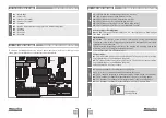
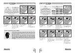
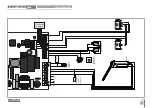
CN1
CN2
CN3
CN4
CN5
Dipper
LS LO FO
LA
FC
LE
3A
3B
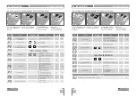
EN
EN
CN4
01
• Safety Edge
02
• Photocells
03
• Encoder (not used)
04
• Encoder (not used)
05
• Common
CN5
01
• +24V DC Auxiliary Power Supply for LED RGB flashing light
02
• Y output
03
• R output
04
• G output
05
• B output
LED
s
LS
• LED lit when the pedestrian push button is active
LO
• LED lit when the total push button is active
F0
• LED off when the opening limit switch is active
FC
• LED off when the closing limit switch is active
LA
• LED off when safety edge is active (when
P6
is active)
LE
• LED off when photocells are active (when
P5
is active)
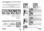
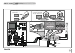
CN1
Courtesy light or flashing light:
08
and
09
• This output allows connection of a courtesy light or a flashing light
(see
P8
in page 10B).
CN2
Limit switches:
03
and
04
• The control board needs a opening and closing limit-switches
connection (both in NC). Triggering any limit-switch will make the immediate
stoppage of the movement.
The limit-switch thriggering is visible on the display. OP (opening limit switch
activated) and CL (opening limit switch activated).
It is mandatory the use of limit switches.
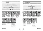
CN4
Safety circuits:
01
• This input allows connection of safety bands. The device operates according
to programming set in the
P6
menu
(page 9A).
02
• This input allows connection of photocells. The device operates according
to programming set in the
P5
menu
(page 8B).
Shunt application is not necessary.
CN5
01
• Auxiliary output for flashing light or 24V DC LED.
Open collector for the management of auxiliary functions:
02
• The Y output is activated in intermittent mode, only with the closed barrier.
03
• The R output is activated in intermittent mode, only in closing phase.
04
• The G output is activated in intermittent mode, only in opening phase.
05
• The B output is activated in intermittent mode, only in pause time.
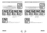
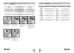
Dipper
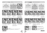
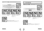
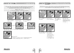
PROGRAMMING PRE-RECOMENDATIONS
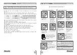
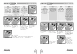
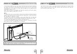
02. THE CONTROL BOARD
02. THE CONTROL BOARD
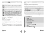
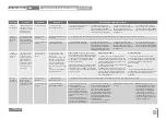
TECHNICAL SPECIFICATIONS
To enhance knowledge about the control board operation, before proceeding to the
setup, give special attention to the instructions that follow.
PROGRAMMING PRE-RECOMENDATIONS
02. THE CONTROL BOARD
Put the dipper
in this position.