
17
16
EN
INSTRUCTIONS FOR FINAL CONSUMERS/TECHNICIANS
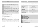
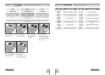
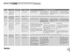
08. TROUBLESHOOTING
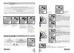
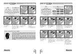
Anomaly
Procedure
Behavior
Procedure II
Discovering the origin of the problem
• Motor
doesn't work
• Make sure you have
230V power supply
connected to control
board and if it is
working properly
• Still not working.
• Consult a qualified
MOTORLINE technician.
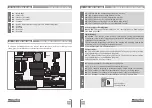
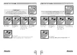
• Motor
doesn’t move
but makes
noise
• Unlock motor and
move the barrier by
hand to check for
mechanical problems
on the movement
• Encountered
problems?
• Consult a qualified barrier
technician.
1 • Check motion axis and associated motion systems related with the motor and the barrier to find out what is the problem.
• The barrier moves
easily?
• Consult a qualified
MOTORLINE technician.
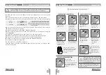
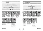
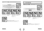
• Barrier
doesn’t make
complete
route
• Unlock motor and
move the barrier
by hand to closed
position. Lock motor
again and turn of
power supply for 5
seconds. Reconnect
it and send order to
open barrier using
transmitter.
• Barrier opened
but didn’t close
again.
1 • Check if there is any
obstacle in front of the
photocells;
2 • Check if any of the con-
trol devices (key selector,
push button, video inter-
com, etc.) of the barrier
are jammed and sending
permanent signal to control
unit;
3 • Consult a qualified MO-
TORLINE technician.
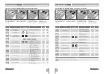
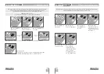
• Motor
opens but
doesn’t close
• Unlock motor and
move barrier by
hand to check for
mechanical problems
on the barrier.
• Encountered
problems?
• Consult a qualified
barrier technician.
1 • Check all motion axis and associated motion systems related with the barrier to find out what is the problem.
• The barrier moves
easily?
• Consult a qualified
MOTORLINE technician.
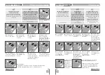
1
• Open control box and check if
it has 230V power supply;
2 • Check input fuses;
3 • Disconnect barrier from
control board and test them by
connecting directly to power
supply in order to find out if they
have problems (see page 15A).
4 • If the barrier works, the
problem is on the control board.
Pull it out and send it to our
MOTORLINE technical services
for diagnosis;
5 • If the barrier doesn’t work,
remove them from installation
site and send to our MOTORLINE
technical services for diagnosis.
1
• Check capacitors, testing
operator with new capacitor;
2 • If capacitors are not the
problem, disconnect motor from
control board and it them by
connecting directly to power
supply in order to find out if it
has problems (see page 15A).
3 • If the motor works, the
problem is from control board.
Pull it out and send it to our
MOTORLINE technical services
for diagnosis;
4 • If the motor doesn’t work,
remove them from installation
site and send to our MOTORLINE
technical services for diagnosis.
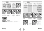
1
• Check capacitors, testing
with new capacitors;
2 • If capacitors are not the
problem, disconnect motor
from control board and test it
by connecting directly to power
supply in order to find out if it is
broken;
3 • If the motor doesn’t work,
remove it from installation site
and send to our MOTORLINE
technical services for diagnosis.
4 • If motor work well and move
barrier at full force during the
entire course, the problem is
from controller. Set force using
trimmer on the board. Make a
new working time programming,
giving suffient time for opening
and closing with appropriate
force (page 08.B of this manual
for MBM6 230V).
5 • If this doesn’t work, remove
control unit and send it to
MOTORLINE technical services
services.
NOTE:
Setting force of the
controller should be sufficient
to make the barrier open and
close without stopping, but
should stop and invert with a
little effort from a person. In
case of safety systems failure,
the barrier shall never cause
physical damaged to obstacles
(vehicles, people, etc.).
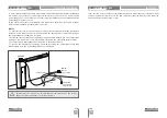
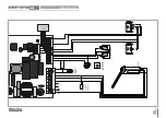
All MOTORLINE control boards have LEDs
that easily allow to conclude which devices
are with anomalies. All safety devices LEDs
(LA and LE) in normal situations remain
On. All "START" circuits LEDs in normal
situations remain Off.
If LEDs devices are not all On, there is some
security systems malfunction (photocells,
safety edges), etc. If "START" circuits LEDs
are turn On, there is a control device sending
permanent signal.
A) SECURITY SYSTEMS:
1 • Close with a shunt all safety systems
on the control board (check manual of the
control board in question). If the automated
system starts working normally check for
the problematic device.
2 • Remove one shunt at a time until you find
the malfunction device .
3 • Replace it for a functional device and
check if the motor works correctly with all
the other devices. If you find another one
defective, follow the same steps until you
find all the problems.
B) START SYSTEMS:
1 • Disconnect all wires from LS and LO
terminal input (terminal 3 of CN3 connector).
2 • If the LED turned Off, try reconnecting
one device at a time until you find the
defective device.
NOTE:
In case procedures described in sections
A) and B) don’t result, remove control board
and send to our technical services for
diagnosis.


