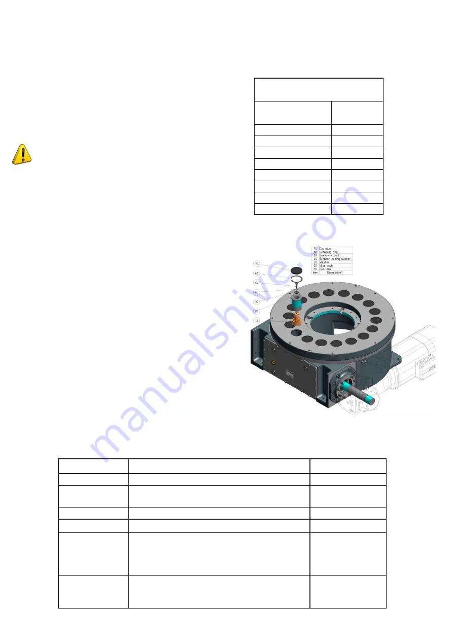
5.1 Removing the Cam Follower
Start by removing the cap plug (item 70). Then use the cir-
clip pliers to remove the retaining ring (item 60). After the
hexagonal bolt (item 50, including 40 and 30) has been re-
moved, together with the two washers, an internal thread
becomes accessible in the cam follower insert. Screw the
internal extractor into the internal thread of the cam follow-
er insert. After applying a lubricant, thecam follower insert is
then carefully pulled from the top dial using the internal ex-
tractor.
Steps must be taken to ensure that no foreign bodies can get
inside the barrell cam rotary indexing table. It is therefore re-
commended that the holes from which the cam follower insert
have been withdrawn should be covered.
It is easier to remove the cam follower if the cylindrical sur-
face is heated. As soon as this has been done, a suitable
bolt can be used to press the cam follower out.
5.2 Installing the Cam Follower
The cam follower insert (item 20) is heated in order to facili-
tate insertion of the cam follower (item 10). After the cam
follower has been pressed into the cam follower insert, we
recommend that you wait for a short time for the insert to
cool before continuing assembly. In the following order, fit
the washer (item 30), the Schnorr locking washer (item 40)
and the hexagonal bolt (item 50). Tighten the bolt to the
maximum torque (see torque table). To facilitate installation
of the cam follower insert (item 20) with the cam follower,
you should cool the insert. Once cooling is complete, press
the insert into the correct hole in the top dial without can-
ting. The cam follower insert is held in position by the circlip
(item 60). The cap plug must be pressed into the correspon-
ding hole so that it is approximately 0.5 mm below flush.
The cap plugs must not protrude from the top dial. Check
the positions of the cap plugs again before the barrel cam
rotary indexing table is taken into operation.
TORQUE TABLE
Steel bolts
(Grade 8.8)
Torque (Nm)
M4
3.3
M5
6.5
M6
11.3
M8
27.3
M10
54
M12
93
M14
148
M16
230
Interval
Maintenance Activity
Staff
Daily
General visual and acoustic inspection.
Operator
Monthly
Check that no oil is escaping from the cylinder
cam rotary indexing table.
Operator
Monthly
Check oil level.
Operator
Monthly
Lubricate the rotary indexing table.
Qualified Staff
Six-Monthly
Visual inspection for damage.
Remove any dust deposits (especially on venti-
lation grills of the drive unit).
Inspect electric cables for damage.
Qualified Staff
Six-Monthly
TMF8000
Visual inspection of the belt drive.
Replace belt drive if necessary.
Qualified Staff
5.3 Maintenance Plan
Содержание RT100
Страница 1: ...TMF SERIES MANUAL ...