background image

21 

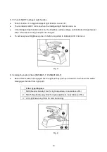
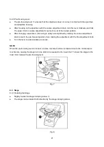
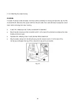
8.2.3 Pre-focusing Lever 

● 

The pre-focusing lever 

 ensures that the objectives does not come in contact with the specimen 


and simplifies focusing. 

● 

After focusing on the specimen with the coarse adjustment knob, turn this lever clockwise and lock. 


The upper limit on coarse adjustment movement is set at the locked position. 

● 

After changing a specimen, refocusing is easily accomplished by rotating the coarse adjustment 


knob to reach the pre-focused position, then making fine adjustment with the fine adjustment knob. 

● 

Turn the lever counterclockwise to unlock. 


NOTE 

When the pre-focusing lever is locked, a coarse movement stroke is reduced due to the 

microscope’s 

mechanism, causing the stage not to be able to be lowered to the lower limit. To lower the stage to the 

lower limit, release the pre-focusing lever. 


Fig. 7 


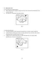
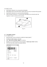
8.3  Stage 

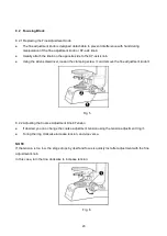
8.3.1 Rotating the Stage 

● 

Slightly loosen the stage clamping screw 

● 

The stage can be rotated both direction by the stage clamping screw. 


Fig.8 

Содержание PA53MET

Страница 1: ...to be entirely accurate at the time of publication MOTIC assumes no responsibility however for possible errors or omissions or for any consequences resulting from the use of the information contained...

Страница 2: ...nclature 13 7 Observation Procedure 16 7 1 Preparation 16 7 2 Procedure 16 8 Operation 18 8 1 Base 18 8 1 1 Voltage Indication and Switch 18 8 1 2 Turn ON OFF Power saving function 18 8 1 3 Turn ON OF...

Страница 3: ...Computer Control 27 9 Troubleshooting Guide 28 9 1 Electrical system 28 9 2 Optical system 28 9 3 Observation Tube 30 9 4 Stage and Focus Adjustment 30 10 Specifications 31 10 1 Body unit 31 10 2 3D m...

Страница 4: ...for this reason that the following safety notices have been placed appropriately within the text of this manual to highlight safety related information or information requiring special emphasis All us...

Страница 5: ...fety ground is fastened to the chassis Protective earth connected to conductive parts of Class I equipment for safety purposes This symbol identifies Alternating Current Disposal of your old appliance...

Страница 6: ...ment is subject to excessive shocks or vibrations Where equipment is exposed to chemical material or explosive gas Pull out the power cord with holding the plug not the cord To avoid risk of electric...

Страница 7: ...rsons Customer maintenance of this equipment may only be performed as stated in the User s Manual and Service Manual Any additional maintenance may only be performed by MOTIC s service technicians or...

Страница 8: ...ternational Detachable Rated 10 A 250 V Plug type CEE 7A II Connector type IEC 60320 C13 and Cord type H05W F3G min 0 75 mm2 3 conductor terminating in molded on grounding type attachment plug HAR mar...

Страница 9: ...tion against harmful interference when the equipment is operated in a commercial environment This equipment generates uses and can radiate radio frequency energy and if not installed and used in accor...

Страница 10: ...below 100 The device can be in the following storage conditions after unpackaged A Temperature range from 10 C to 55 C B Relative humidity range below 95 The device is made to operate under the follo...

Страница 11: ...cus adjustment knob binocular tube lamp housing and stage It may cause serious damage to the microscope The desktop should be a level surface with an inclination of less than 3 The microscope may beco...

Страница 12: ...lames or potential sources of electrical sparks for example electrical equipment that is being switched on or off Also remember to always use it only in a well ventilated room Do not attempt to use or...

Страница 13: ...13 6 NOMENCLATURE...

Страница 14: ...14...

Страница 15: ...15 Control box and control pad are provided PA53MET 3D PA53MET BD 3D only...

Страница 16: ...ocus the specimen Coarse fine adjustment knob Adjust brightness Brightness control knob Adjust diopter if light path selection is eye Diopter adjustment ring Adjust interpupillary distance if light pa...

Страница 17: ...17...
Страница 18: ...the voltage and make illumination brighter and vice versa The indicator indicate the voltage Fig 1 8 1 2 Turn ON OFF Power saving function Push ECO button to toggle power saving function on and off T...

Страница 19: ...ng nosepiece is changed To set new preset brightness press IL button long while IL indicator LED turns on Fig 3 8 1 4 Using the built in Filters PA53MET T PA53MET BD T Each of filter switch can engage...

Страница 20: ...he Allen screwdriver loosen the clamping screw and remove the fine adjustment knob Fig 5 8 2 2 Adjusting the Coarse Adjustment Knob Tension If desired you can change the coarse adjustment tension usin...

Страница 21: ...d by rotating the coarse adjustment knob to reach the pre focused position then making fine adjustment with the fine adjustment knob Turn the lever counterclockwise to unlock NOTE When the pre focusin...

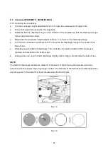
Страница 22: ...llary distance Fig 9 8 4 2 Adjusting the Diopter The diopter adjustment ring is used when the eyepiece has no function of diopter adjustment Looking through the right eyepiece there is no diopter adju...

Страница 23: ...asses extend the folded eye shades in direction of the arrow to prevent extraneous light from entering between the eyepieces and eyes Fig 11 8 4 4 Selecting the Light Path of the Trinocular Tube Slide...

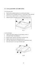
Страница 24: ...nser centering knob to move the iris diaphragm image to the center of the field of view Gradually open the field iris diaphragm The condenser is properly centered if the iris image is centered and ins...

Страница 25: ...roscope specimens is ordinarily low setting the condenser aperture iris diaphragm to between 70 and 80 of the NA of the objectives in use is usually recommended Remove one of the eyepieces look into t...

Страница 26: ...cision of control Rotate the fine focus adjustment knob to change voltage of lamp Fig 17 8 6 2 Height display Height of 3D profiler is displayed in height display window Two type of height can be disp...

Страница 27: ...y stop button to stop 3D profiler immediately Use this button when the objectives is about to contact with the specimen Fig 19 8 7 Linking Motic Analysis 8 7 1 Computer Control Some parameter can be c...

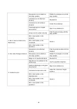
Страница 28: ...s not connected securely Connect it securely Lamp is not collected securely Insert it securely 9 2 Optical system Problem Cause Remedy 1 Lamp lights but field of view is dark Lamp voltage is too low A...

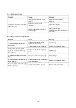
Страница 29: ...s on the condenser Dirt or dust exists on the specimen 4 One side of image is blurred Nosepiece is not attached properly Push the slide dovetail until it is stopped Nosepiece is not rotated to a click...

Страница 30: ...oarse adjustment knob is hard to turn Tension adjustment ring is tightened excessively Loosen ring Focus stopper lever is locked Unlock focus stopper lever 2 Stage falls down by itself Image is out fo...

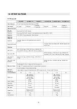
Страница 31: ...D 0 5mm Optional Plan S APO BD 5X 0 15 W D 20mm 10X 0 3 W D 12mm 20X 0 45 W D 3mm 50X 0 8 W D 1mm 100X 0 9 W D 0 5mm Optional LPlan S APO Optional 20X 0 4 W D 12mm 50X 0 55 WD 8mm 100X 0 8 W D 3 3mm...

Страница 32: ...ulb Philips 7724 12V 100W long life halogen bulb Philips 7724 Condenser No Yes No Yes Abbe N A 1 20 N A 1 20 Long working LWCD N A 0 65 LWCD N A 0 65 Stage 4x4 inch Size 210 W X 170 D mm Stroke 104 X...

Страница 33: ...nification N A W D mm Cover glass Thickness mm Field of view mm Eyepiece 10x Plan S Apo 5x 0 15 20 0 5 10x 0 30 12 0 2 5 20x 0 45 3 0 1 25 50x 0 80 1 0 0 5 100x 0 90 0 5 0 0 25 Plan S Apo BD 5x 0 15 2...

Страница 34: ...of assembly of the various modules When assembling the microscope make sure that all parts are free of dust and dirt and avoid scratching any parts or touching glass surfaces Most assembly operations...

Страница 35: ...e bulb with gloves or a piece of gauze depress the bulb clamping lever and insert bulb pin fully into the pin holes on the lamp socket Gently release the bulb clamping lever to the original position t...

Страница 36: ...d down before removing the Lamp housing Loosen the clamping screw with provided Allen screwdriver Mount the lamp housing to the connection port on the rear of the illuminator and press the lamp housin...

Страница 37: ...lowest position Fully loosen the condenser clamping knob Position the condenser so that the aperture scale is located in front Tighten the condenser clamping knob and gently raise the condenser holde...

Страница 38: ...and tighten the observation tube clamp screw Fig 26 11 2 6 Attaching the Eyepiece NOTE Attach eyepieces of the same magnification and of the same field number to the left and the right eyes Otherwise...

Страница 39: ...e and fasten it Connect main body connector withanother end of 12pin cable and fasten it Connect controlpad connecter withprovided 6pin cable and fasten it Connect controlbox connector withanother end...

Страница 40: ...40 11 2 8 Attaching the Computer Connect Motic Analysis port and computer with RS232C cable when using Analysis program Fig 29...

Отзывы: