background image


2.2.4.2 Computer Ports Description 

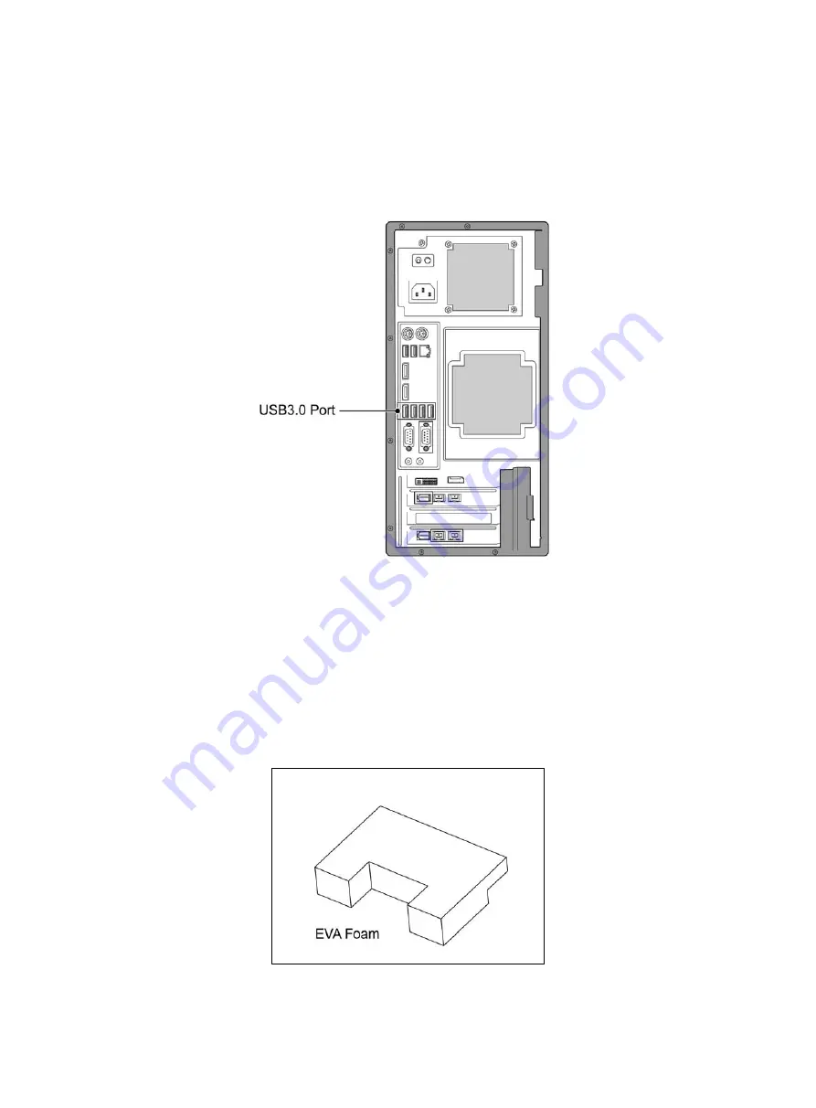
USB port of host computer should be USB3.0 port, which is signed with SS or marked as blue color.   


Computer Ports Diagram 

(Fig. 4) 


2.2.5 System Connection Operation 

Please make sure the EVA foam, which is inside the device, is taken out before starting any operation 

and connection work. (Fig. 5) 


(Fig. 5) 

Содержание 1100300500438

Страница 1: ... If the equipment is used in a manner not specified by the manufacturer the protection provided by the equipment may be impaired Note Complete reading of this manual before opeartion is required WWW MOTIC COM MOTIC HONG KONG LIMITED ...

Страница 2: ...tion 7 2 2 4 1 Device Hosting Ports Description 7 2 2 4 2 Computer Ports Description 8 2 2 5 System Connection Operation 8 2 3 Slide Tray 10 2 3 1 Placement Procedure 10 2 3 1 1 Slide Loading Procedure 10 2 3 1 2 Slide Unloading Procedure 11 2 3 2 Slide Tray Installation Procedure 12 3 Software Installations and Instructions 13 3 1 Software Installation 13 3 2 User Interface 17 3 3 Slide Scanning ...

Страница 3: ... Image 24 5 2 3 Calibration 25 5 2 3 1 Import Calibration File 25 5 2 3 2 Auto Calibration 26 5 2 3 3 Manual Calibration 27 6 Appendix 34 6 1 Specifications 34 6 2 Electrical Specification 34 6 3 Working Environment 34 6 4 Storage Environment 34 6 5 Digital Camera System Specifications 35 6 6 Device Movement 35 6 7 Component Purchasing 35 6 7 1 Accessory List 35 6 8 Miscellaneous 36 6 9 Lens Clean...

Страница 4: ...y of the general danger Follow the descriptions on the back of signs or follow manufacturer s instructions For damaged missing or unreadable labels please contact Motic Group Corporation for replacement before continue operation 1 3 Device Safety and EMC MoticEasyScan One is designed manufactured and inspected in accordance with the IEC 61010 1 2001 EN 61010 1 2001 and GB4793 1 2007 safety standar...

Страница 5: ... to the instruction in the Manual Please note the following warranty for MoticEasyScan One Manufacturer warranty for material and product quality starts at the time of delivery In case of malfunction please inform the manufacturer immediately If being notified of such a defect the manufacturer is obligated to repair the device or deliver an intact replacement Manufacturer does not assume warranty ...

Страница 6: ...d with Motic digital slide scanning software It is applicable for scanning digital storage transferring and browsing of histopathology slide cytology and biology slides etc MoticEasyScan One can be remotely controlled through software 2 2 System Overview 2 2 1 System Diagram This product consists of device main body slide tray and scanning software If the equipment is used in manner not specified ...

Страница 7: ...6 2 2 2 System Installation Before installation please be familiar with following parts USB 3 0 cable Power Supply Cable 2 2 3 System Connection Diagram Fig 2 ...

Страница 8: ...7 2 2 4 Port Description 2 2 4 1 Device Hosting Ports Description USB port matches macro camera and main camera USB cable connects to USB3 0 port of host computer Fig 3 ...

Страница 9: ...should be USB3 0 port which is signed with SS or marked as blue color Computer Ports Diagram Fig 4 2 2 5 System Connection Operation Please make sure the EVA foam which is inside the device is taken out before starting any operation and connection work Fig 5 Fig 5 ...

Страница 10: ...the locking screw Fig 6a Then slide the front panel out in horizontal direction from the device Fig 6a Take out the EVA foam carefully Fig 6b Snap the front panel back into the device and relock the locking screw Fig 6b Fig 6a Fig 6b ...

Страница 11: ...cEasyScan One is offered with 1 slide tray Fig 7 2 3 1 Placement Procedure 2 3 1 1 Slide Loading Procedure Hold the two sides of the slide with the thumb and index finger barcode position is in the direction of Fig 7 follow the direction of Fig 8a load the slide under the clip Fig 7 with 15 degree angle then push it to the end after adjusting to correct angel Push down the barcode in the direction...

Страница 12: ...lot need to check if the slide is loaded onto the flat mounting pads d Do not touch the cover glass on the slide during the whole process Fig 8a Fig 8b Fig 8c 2 3 1 2 Slide Unloading Procedure Hold the slide with index finger and thumb unload the slide towards direction of clip Fig 7 to the bottom until the other side can be lifted Fig 9a then lift the slide upward with 15 degree to move out of th...

Страница 13: ...g 9a Fig 9b 2 3 2 Slide Tray Installation Procedure 1 Load the slide tray into slide tray positioning slot slightly with the direction make sure the arrow on the tray is outward shown in the figure 10 Fig 10 ...

Страница 14: ...LLATIONS AND INSTRUCTIONS 3 1 Software Installation a The software should be installed by administrators Double click Setup exe file in the installation program b Select installation language and click on the Next button ...

Страница 15: ...14 c Then click Next button d Select installation path and click Next button ...

Страница 16: ...15 e Select installation path and click Next button f Click Install button to proceed installation and display installation process ...

Страница 17: ...16 g Select EasyScan 1 configuration and then click OK button h When installation is completed click Finish button to complete software installation ...

Страница 18: ...from grey to blue then click Scan for automatic scanning Main function is described as below a Scan Click the slide for scanning b Scanning mode selection frame can select Standard High Precision EDF and Z Stacking Standard is the default mode c Slide name edit frame if slide has barcode it will be automatically identified and name it with the time to date if there is no barcode then it will be na...

Страница 19: ...es floating fixed window design the user can customize the window layout all windows can be set as floating fixed or hidden type System will automatically save current window layout and take it as the default window next time when running the program Note If View is selected in the menu go to submenu lock interface then all the windows will be fixed and cannot be dragged or moved System provides a...

Страница 20: ...ve picture shown During scanning scanner will only scan the inner part of the green outline and automatically skip over the outside empty part When you click on the view of macro picture on the operation interface it will display the Scan Area Editor window as below shown Edit Mask turn on off the function of editable tissue outline Auto detect scan area automatically with green curve outline Add ...

Страница 21: ...eeded After clicking Scan button the scanning will be performed based on interface settings When scanning is completed a message will be displayed for next step operation The digital slide image can be viewed by double clicking the macro map or via Motic DSAssistant Followings are MoticEasyScaner software slide scanning characteristics Using macro camera to get macro map of the slide about 7 8 sec...

Страница 22: ...r establishing auto focusing modeling ii To adjust modeling area move the mouse on the red frame line and hold the left mouse button to drag then the dimension of red bold line frame will be changed iii If user does not need to do modeling in this area click the mouse left button on the map to cancel modeling area and the red frame will be disappeared Set modeling point system will automatically d...

Страница 23: ...anning area Select scanning method on right side of the map frame Standard High Precision EDF and Z Stacking Click Scan slide button start scanning and image acquisition 3 4 For Mobile Device Optional MoticEasyScan One can be remotely controlled by installing wireless router on mainframe of scanner computer and connect the mobile device to the router By doing this it can realize scanner controllin...

Страница 24: ...s to perform a reset and the Status Light Indicator flashes with a high frequency c Load the slide tray into slide stray positioning slot slightly and stop loading when it is 5 8mm left Then the slide tray will be transfered leftward to the right position and the Status Light Indicator will stay on d At this moment the Scan button is effective on the operation interface One button scanning can be ...

Страница 25: ...e fuse of the same type f Turn off the power when the device is not in use 5 2 Troubleshooting 5 2 1 Software cannot control MoticEasyScan One Operation Check if MoticEasyScan One is securely connected to computer USB3 0 cable Restart the computer and verify that no other program uses the computer serial port turn on off MoticEasyScan One power 5 2 2 Scanning Software is not able to Display Image ...

Страница 26: ...xported the correct calibration data before reinstalling or updating the software Go to System Calibration click Save and Export button then it will save the calibration data to a file Note Generally you can do it as a backup file when the EasyScan is in a good condition or you finished all calibration b Go to System Calibration click Import button and select the backup calibration file ...

Страница 27: ...peration It is fit for only changing the objective scanning poor quality images a Auto Calibration Settings Follow the wizard select a blank spot a tissue spot entire tissue region in the map b As shown in the following figure it will automatic complete system calibration macro calibration and focus calibration ...

Страница 28: ...remove the slide first and click this button the system will automatically process Exposure Background Balance White Balance Video Scale Calibration For implementation of video scale calibration Field of view width height um displays the calibration results of corresponding horizontal and vertical video scale Calibrate start to perform the calibration operation ...

Страница 29: ...sults of camera angle Calibrate start to perform calibration operation Please read the calibration conditions before calibration Focus Reference Position Calibration Focus reference position calibration is to obtain clear focal plane after focusing Referent position um shows focal plane calibration results of Z axis corresponding to 40x objective Calibrate start to perform calibration operation ...

Страница 30: ...y with slide which has shape tissue and label on it Then please follow the calibration wizard Fig B Click Prepare Tissue Exposure on the calibration wizard window then tray will step back You will find the marco camera s field of view is blank Ensure the tray does not exist on the device Adjust the exposure bar to let the histogram close to red bar Fig A Click Set Tissue Image on the calibration w...

Страница 31: ...ion Manually adjust the exposure bar and ensure the brightness of label is suitable Complete Macro Image Settings Select an area which can cover whole tissue by dragging a rectangle over it with the mouse Then click Scan Map button After scanning map is completed click Calibrate button to complete calibration Fig D Fig A ...

Страница 32: ...31 Fig B Fig C ...

Страница 33: ... the steps of 10 and 11 Fig B Fig D Select an area which can cover whole tissue by dragging a rectangle over it with the mouse Then click Scan Map button After scanning map completed click Calibrate button to complete calibration ...

Страница 34: ...d with content focus the image move to the blank area of slide adjust exposure ensure the right half of histogram has no saturation Click Background Balance button in the blank area of slide Find a field filled with contents and adjust to focal plane check the value of Focus Pos if it is greater or equal 0 1 the par focal settings of the hardware should be adjusted if it is less than 0 1 then clic...

Страница 35: ...mera 5M Pixel Communication Port USB 3 0 6 2 Electrical Specification Input voltage 100 240V 50 60Hz Input power 100VA FUSE 250V T2 5AL If damaged replace the fuse with the same specifications 6 3 Working Environment For indoor use Altitude within 2000m Higher than this altitude needs to be revised accordingly based on international coefficient Environment temperature 5 C 40 C Humidity 30 75 No co...

Страница 36: ... respectively during lifting and handling process need to keep balance of device to prevent rollover If you need to pack MoticEasyScan One for long distance transportation please contact Motic or the Motic Distributor Fig 13 6 7 Component Purchasing To guarantee product performance except standard components ie Power cable screws ect please be sure to purchase other components from Motic or Motic ...

Страница 37: ...tor or the socket is placed in the place where you can remove the power cord Please keep this device in the environment with good ventilation Please do not place the device in position which is difficult to disconnect power cable connector Please do not put non relevant stuff on the device When replacing the fuse please refer to the label parameter FUSE 250V T2 5AL near the equipment power socket ...

Страница 38: ...arcelona Spain Tel 34 93 756 6286 Fax 34 93 756 6287 Website http www motic com E mail info motic com hk Motic China Group Ltd China Motic Building Torch Hi Tech Industrial Development Zone Xiamen P R C Tel 86 0592 562 7866 Fax 86 0592 562 7855 2007 2017 Motic China Group Co Ltd All rights reserved Motic is a registered trademark and service mark of Motic China Group Co Ltd Microsoft Windows logo ...

Отзывы: