


7-6
Section 7: System Description
Moseley SL9003Q
602-12016-01 Revision J
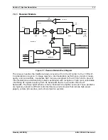
Figure 7-6. SL9003Q Receiver System Block Diagram
All modules (excluding the Front Panel) are interconnected via the Backplane which
traverses the entire width of the unit. The Backplane contains the various communication
buses as well as the redundant transfer circuitry. The power supply levels and status are
monitored and the NMS/CPU card processes the data.
The NMS/CPU card incorporates microprocessor and FPGA logic to configure and monitor the
overall operation of the system via front panel controls, LCD screen menus, status LEDs and
the bar graph display. Module settings are loaded into the installed cards. Power-up default
settings are stored in non-volatile memory. LCD menu software is uploaded into memory,
providing field upgrade capability. A Windows-based PC interface is available for connection
at the rear panel DATA port.
Содержание Starlink SL9003Q
Страница 25: ...Section 2 Quick Start 2 9 Moseley SL9003Q 602 12016 01 Revision J Figure 2 4 Radio TX Status Performance Check ...
Страница 86: ...5 22 Section 5 Module Configuration Moseley SL9003Q 602 12016 01 Revision J ...
Страница 90: ...6 4 Section 6 Customer Service Moseley SL9003Q 602 12016 01 Revision J ...
Страница 109: ...Appendix A Path Evaluation Information A 9 Moseley SL9003Q 602 12016 01 Revision J A 2 7 Path Calculation Balance Sheet ...
Страница 110: ...A 10 Appendix A Path Evaluation Information Moseley SL9003Q 602 12016 01 Revision J ...
Страница 118: ...D 2 Appendix D Microvolt dBm Watt Conversion 50 ohms Moseley SL9003Q 602 12016 01 Revision J ...
Страница 140: ...G 4 Appendix G Optimizing Radio Performance For Hostile Environments Moseley SL9003Q 602 12016 01 Revision J ...