

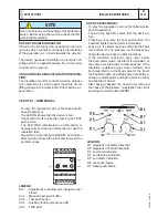


ELECTRICAL SYSTEM LEGENDE
M
60
REV.9-06/11
26/07/04 M60GB
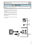
A
: Alternator
B
: Wire connection unit
C
: Capacitor
D
: G.F.I.
E
: Welding PCB transformer
F
: Fuse
G
: 400V 3-phase socket
H
: 230V 1phase socket
I
: 110V 1-phase socket
L
: Socket warning light
M
: Hour-counter
N
: Voltmeter
P
: Welding arc regulator
Q
: 230V 3-phase socket
R
: Welding control PCB
S
: Welding current ammeter
T
: Welding current regulator
U
: Current transformer
V
: Welding voltage voltmeter
Z
: Welding sockets
X
: Shunt
W
: D.C. inductor
Y
: Welding diode bridge
A1 : Arc striking resistor
B1 : Arc striking circuit
C1 : 110V D.C./48V D.C. diode bridge
D1 : E.P.1 engine protection
E1 : Engine stop solenoid
F1 : Acceleration solenoid
G1 : Fuel level transmitter
H1 : Oil or water thermostat
I1
: 48V D.C. socket
L1 : Oil pressure switch
M1 : Fuel warning light
N1 : Battery charge warning light
O1 : Oil pressure warning light
P1 : Fuse
Q1 : Starter key
R1 : Starter motor
S1 : Battery
T1 : Battery charge alternator
U1 : Battery charge voltage regulator
V1 : Solenoid valve control PCBT
Z1 : Solenoid valve
W1 : Remote control switch
X1 : Remote control and/or wire feeder socket
Y1 : Remote control plug
A2 : Remote control welding regulator
B2 : E.P.2 engine protection
C2 : Fuel level gauge
D2 : Ammeter
E2 : Frequency meter
F2 : Battery charge trasformer
G2 : Battery charge PCB
H2 : Voltage selector switch
I2
: 48V a.c. socket
L2 : Thermal relay
M2 : Contactor
N2 : G.F.I. and circuit breaker
O2 : 42V EEC socket
P2 : G.F.I. resistor
Q2 : T.E.P. engine protection
R2 : Solenoid control PCBT
S2 : Oil level transmitter
T2 : Engine stop push-button T.C.1
U2 : Engine start push-buttonT.C.1
V2 : 24V c.a. socket
Z2 : Thermal magnetic circuit breaker
W2 : S.C.R. protection unit
X2 : Remote control socket
Y2 : Remote control plug
A3 : Insulation moitoring
B3 : E.A.S. connector
C3 : E.A.S. PCB
D3 : Booster socket
E3 : Open circuit voltage switch
F3 : Stop push-button
G3 : Ignition coil
H3 : Spark plug
I3
: Range switch
L3 : Oil shut-down button
M3 : Battery charge diode
N3 : Relay
O3 : Resistor
P3 : Sparkler reactor
Q3 : Output power unit
R3 : Electric siren
S3 : E.P.4 engine protection
T3 : Engine control PCB
U3 : R.P.M. electronic regulator
V3 : PTO HI control PCB
Z3 : PTO HI 20 l/min push-button
W3 : PTO HI 30 l/min push-button
X3 : PTO HI reset push-button
Y3 : PTO HI 20 l/min indicator
A4 : PTO HI 30 l/min indicator
B4 : PTO HI reset indicator
C4 : PTO HI 20 l/min solenoid valve
D4 : PTO HI 30 l/ min solenoid valve
E4 : Hydraulic oil pressure switch
F4 : Hycraulic oil level gauge
G4 : Preheating glow plugs
H4 : Preheating gearbox
I4
: Preheating indicator
L4 : R.C. filter
M4 : Heater with thermostat
N4 : Choke solenoid
O4 : Step relay
P4 : Circuit breaker
Q4 : Battery charge sockets
R4 : Sensor, cooling liquid temperature
S4 : Sensor, air filter clogging
T4 : Warning light, air filter clogging
U4 : Polarity inverter remote control
V4 : Polarity inverter switch
Z4 : Transformer 230/48V
W4 : Diode bridge, polarity change
X4 : Base current diode bridge
Y4 : PCB control unit, polarity inverter
A5 : Base current switch
B5 : Auxiliary push-button ON/OFF
C5 : Accelerator electronic control
D5 : Actuator
E5 : Pick-up
F5 : Warning light, high temperature
G5 : Commutator auxiliary power
H5 : 24V diode bridge
I5
: Y/
s
commutator
L5 : Emergency stop button
M5 : Engine protection EP5
N5 : Pre-heat push-button
O5 : Accelerator solenoid PCB
P5 : Oil pressure switch
Q5 : Water temperature switch
R5 : Water heater
S5 : Engine connector 24 poles
T5 : Electronic GFI relais
U5 : Release coil, circuit breaker
V5 : Oil pressure indicator
Z5 : Water temperature indicator
W5 : Battery voltmeter
X5 : Contactor, polarity change
Y5 : Commutator/switch, series/parallel
A6 : Commutator/switch
B6 : Key switch, on/off
C6 : QEA control unit
D6 : Connector, PAC
E6 : Frequency rpm regulator
F6 : Arc-Force selector
G6 : Device starting motor
H6 : Fuel electro pump 12V c.c.
I6
: Start Local/Remote selector
L6 : Choke button
M6 : Switch CC/CV
N6 : Connector – wire feeder
O6 : 420V/110V 3-phase transformer
P6 : Switch IDLE/RUN
Q6 : Hz/V/A analogic instrument
R6 : EMC filter
S6 : Wire feeder supply switch
T6 : Wire feeder socket
U6 : DSP chopper PCB
V6 : Power chopper supply PCB
Z6 : Switch and leds PCB
W6 : Hall sensor
X6 : Water heather indicator
Y6 : Battery charge indicator
A7 : Transfer pump selector AUT-0-MAN
B7 : Fuel transfer pump
C7 : "GECO" generating set test
D7 : Flooting with level switches
E7 : Voltmeter regulator
F7 : WELD/AUX switch
G7 : Reactor, 3-phase
H7 : Switch disconnector
I7
: Solenoid stop timer
L7 : "VODIA" connector
M7 : "F" EDC4 connector
N7 : OFF-ON-DIAGN. selector
O7 : DIAGNOSTIC push-button
P7 : DIAGNOSTIC indicator
Q7 : Welding selector mode
R7 : VRD load
S7 : 230V 1-phase plug
T7 : V/Hz analogic instrument
U7 : Engine protection EP6
V7 : G.F.I. relay supply switch
Z7 : Radio remote control receiver
W7 : Radio remote control trasnsmitter
X7 : Isometer test push-button
Y7 : Remote start socket
A8 : Transfer fuel pump control
B8 : Ammeter selector switch
C8 : 400V/230V/115V commutator
D8 : 50/60 Hz switch
E8 : Cold start advance with temp. switch
F8 : START/STOP switch
G8 : Polarity inverter two way switch
H8 : Engine protection EP7
I8
: AUTOIDLE switch
L8 : AUTOIDLE PCB
M8 : A4E2 ECM engine PCB
N8 : Remote emergency stop connector
O8 : V/A digital instruments and led VRD PCB
P8 : Water in fuel
Q8 : Battery disconnect switch
R8 : Inverter
S8 : Overload led
T8 : Main IT/TN selector
U8 : NATO socket 12V
V8 : Diesel pressure switch
Z8 : Remote control PCB
W8 : Pressure turbo protection
X8 : Water in fuel sender
Y8 : EDC7-UC31 engine PCB
A9 : Low water level sender
B9 : Interface card
C9 : Limit switch
D9 : Starter timing card
E9 : Luquid pouring level float
F9 : Under voltage coil
G9 : Low water level warning light
H9 : Chopper driver PCB
I9
:
L9 :


