Mosa GE 20 YSX Скачать руководство пользователя страница 20

General precautions when handling the machine.

To limit the dangers involved in moving a generating set, 

it  is  important  to  carefully  follow  the  guideline  set  out 

below:

•  Transportation must always take place with the en-

gine off and electrical cables and starting battery di-

sconnected and fuel tank empty.

•  Particular attention must be paid to SKID version ge-

nerating sets (without canopy) that have very delicate 

parts unprotected from bumps (injection pump, speed 

regulator,  radiator,  electrical  panel  connections  and 

instrumentation).

•  Generating sets must be protected from bad weather 

during transport: the units must be entirely covered, 

especially the electrical parts (alternator and control 

panel).

•  Some engine parts retain heat even after it has been 

shut off: therefore it is necessary to wait for the engi-

ne to cool before covering it to avoid the risk of fire.

•  Clear the moving zone of all possible obstacles and 

from all unnecessary personnel.

•  Use properly sized lifting equipment regularly submit-

ted to major overhaul by an authorized organisation. 

It is prohibited to fasten objects or accessories on the 

generating  set  baseframe  that    may  modify  weight 

and center of gravity and may cause movements un-

foreseen by the lifting eyes.

•  Do  not  subject  the  generating  set  and  lifting  equip-

ment to abrupt or undulating movements that pass on 

stress dynamics to the structure.

•  Do not lift the generating set higher than what is ab-

solutely necessary.

•  Transportation of separate manual or automatic con-

trol panels must be carried out very carefully in order 

to avoid damage to the equipment contained inside 

the panel and to the instruments on the front.

•  To access the hook points on the top of the unit, use 

approved ladders only or support from another opera-

tor: climb the ladder using non-skid shoes.
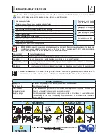
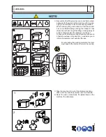
ATTENTION

When moving/lifting a genset it is imperative to be 

extremely careful. All moving operations must be 

carried out be qualified persons.

Due to the weight and encumbrance of the genset, 

an error while moving/lifting the unit may cause 

serious damage to it or surrounding persons.
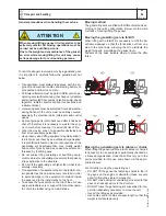
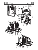
Moving method

The generating sets are lifted with different methods ac-

cording to the unit’s configuration. Below are the main 

methods of moving/lifting the genset.

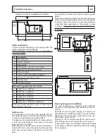
Moving the generating set via forklift 

When lifting with a forklift it is necessary to fork the ba-

seframe sideways so that the forks stick out from one 

side to the other side, widening them to distribute the 

weight properly, maintaining the genset level.

Stickers on the base indicate where to place the lifter 

forks.

Transport  and handling

!

M

4.2

REV.0-06/10

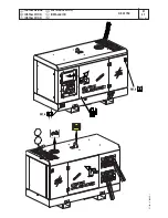
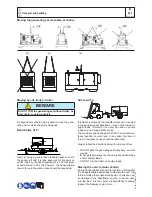
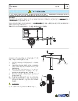
Moving the generating set via cables or chains

When lifting the genset with the aid of cables or chains it 

is necessary to use equipment periodically checked by 

a licensed organisation. Hook the cables only on to the 

points provided for this use and shown via the appro-

priate stickers. 


For correctly moving the generating set:

•  DO NOT lift the genset by fastening cables to the lif-

ting eyes on the engine or alternator (these are only 

used for lifting the single components).

•  DO NOT make abrupt or undulating movements that 

pass on stress dynamics to the structure.

•  DO NOT leave the generating set suspended for lon-

ger than absolutely necessary to move the unit.

•  Use all the lifting eyes provided.

•  Use cables and/or chains of equal length so that the 

weight is distributed evenly.

02/06/10  M4-GB_COF

Содержание GE 20 YSX

Страница 1: ...USE AND MAINTENANCE MANUAL MOSA 25 09 12 84920M00 preparato da UPT approvato da DITE GE 20 YSX 849209003 GB 0 3 1 3...

Страница 2: ...des a tank an engine alternator unit fixed on the base by elastic dampers a roll bar with hook for an easy and sure lifting a chest hinged to the roll bar for a quick access to the engine and to the a...

Страница 3: ...continue to satisfy the needs of its clients aswell as to improve the transparency and thecom munications regarding all the company s activesin accordance with the official procedures and inhar mony w...

Страница 4: ...INSTALLATION M 2 7 INSTALLATION AND DIMENSIONS M 3 UNPACKING M 4 2 TRANSPORT AND HANDLING M 6 20 CTL 20 ASSEMBLY M 20 SET UP FOR OPERATION M 21 START AND STOP M 31 CONTROLS M 32 CONTROLS M 39 12 EP6...

Страница 5: ...matter In no case MOSA division of B C S S p A will be held responsible for any damaga direct or indirect in relation with the use of the given information MOSA division of B C S S p A does not take...

Страница 6: ...mpness and heat You must take into account that some figures contained in it want only to identify the described parts and therefore might not correspond to the machine in your possession INFORMATION...

Страница 7: ...elf the list of these directives is part of the declaration of conformity included in any machine standard equipment Here below the adopted symbol CE marking is clearly readable and unerasable and it...

Страница 8: ...mber ______________________________ conforme con quanto previsto dalle Direttive Comunitarie e relative modifiche est en conformit avec ce qui est pr vu par les Directives Communautaires et relatives...

Страница 9: ...wer PRP maximum available power for use at variable loads for a yearly illimited number of hours The average power to be taken during a period of 24 h must not be over 80 of the PRP It s admitted over...

Страница 10: ...persons or things Do not use without protective devices provided Removing or disabling protective devices on the machine is prohibited Do not use the machine if it is not in good technical condition...

Страница 11: ...ersons Use only with safety clothing It is compulsory to use the personal protection means given in equip ment Use only with safety clothing It is compulsory to use the personal protection means given...

Страница 12: ...tely Wipe up spilled fuel before starting engine An electric shock can kill Shut off fuel of tank when moving machine where it is assembled Avoid spilling fuel on hot engine Sparks may cause the explo...

Страница 13: ...s are equipped with a control system that is NOT influenced by standard environmental fac tors and is able to stop the unit in case of anomalous values in the fundamental parameters In order to avoid...

Страница 14: ...nce no specific mea sures are needed in this regard In case of doubts concerning your genset do not hesitate to contact our technical sales office Installation instructions M 2 6 1 REV 0 06 10 ATTENTI...

Страница 15: ...fix the genset to it by using screw anchors or rag bolts Base dimensions should exceed genset dimensions of at least 200 mm on each side Base should weigh three times static genset weight indicated on...

Страница 16: ...duct should be evaluated If the duct is not appropriately insulated room temperature may in crease considerably for this reason it may be necessary to install an electro ventilator for correct air ex...

Страница 17: ...Installazione Installation Installation Luftzirkulation Instalaci n GE 20 YSX M 2 7 REV 0 09 12 27 09 12 84920 I...

Страница 18: ...Dimensioni Dimensions Dimensions Abmessungen Dimensiones GE 20 YSX M 2 7 1 REV 0 09 12 27 09 12 84920 I...

Страница 19: ...rough handling or taking away of parts contained inside the packing or in the set In case you find damages rough handling or absence of parts envelopes manuals etc we advise you to inform immediately...

Страница 20: ...ide the panel and to the instruments on the front To access the hook points on the top of the unit use approved ladders only or support from another opera tor climb the ladder using non skid shoes ATT...

Страница 21: ...nnected to the generating set baseframe it can not be towed on public roads Therefore it can only be used on private roads and no through traffic zones The maximum speed allowed is 40 km h on smooth s...

Страница 22: ...the machine to the ground and place the parking foot definitively regulating at the suitable height ATTENTION Do not substitute the original tires with other types 7 8 9 Nota Lift the machine and asse...

Страница 23: ...he state of the battery from the colour of the warning light which is in the upper part Green colour battery OK Black colour battery to be recharged White colour battery to be replaced DO NOT OPEN THE...

Страница 24: ...t an easy job A lack in tacking these precautions would result in the mix of different additives used in different coolants which would originate gelatinous substances capable of obstructing the cooli...

Страница 25: ...ng and on the display the word fail appears Turning the key on OFF the EP6 is reset and a new starting cycle can be fixed Stop it is COMPULSORY to disconnect the load first then to stop the engine tur...

Страница 26: ...ing light PTO HI B5 Auxiliary current push button C2 Fuel level light C3 E A S PCB C6 Control unit for generating sets QEA D Ground fault interrupter 30 mA D1 Engine control unit and economiser EP1 D2...

Страница 27: ...Comandi Controls Commandes Mandos GE 20 YSX M 31...

Страница 28: ...ol tage operation messages 15 A C socket AUX sockets for load connection I6 Start Local Remote selector Selection of engine control in use Local start control on board EP6 operated Remote start extern...

Страница 29: ...0 In case of an Automatic Periodic Test A P T the display will show the message tESt 2 2 MANUAL operating mode To start the engine follow the instructions A Turn ON the KEY SWITCH the EP6 illuminates...

Страница 30: ...matically anytime the key switch is turned ON The LEDs and DISPLAY light up for about 1 second 6 0 Parameters and settings The unit is programmed by the supplier of the Gen erating Set Contact the Gen...

Страница 31: ...ing for at least 2 seconds the EP6 will energize the over voltage protection Hi U see section 4 0 to stop the engine The inh code inhibits the over voltage P 8 Generator Under Frequency Inh inh 1 to 9...

Страница 32: ...P 24 P 24 Crank OFF Inh Crank Termination setting 100 800 rpm If the speed rises above the setting the EP6 terminates the crank cycle One sec onddelay avoids false termination The code Inh inhibits t...

Страница 33: ...rror accumulation and in case your unit is programmed to allowAutomatic Periodic Test we recommend the following procedures disconnect the power supply of the EP6 consult your genset supplier wait for...

Страница 34: ...ions and nominal values for voltage frequency power factors cos There are various types of power PRIME POWER PRP STAND BY POWER established by ISO 8528 1 and 3046 1 Norms and their definitions are lis...

Страница 35: ...e motor allows it see to a start up with reduced voltage star point triangle start up or with autotransformer or use a soft start system In all cases when the user circuit requires the start up of an...

Страница 36: ...tection forcefully pressed to prevent its intervention ATTENTION USAGE WITH EAS AUTOMATIC START UP PANEL The electricity generating group in combination with the EAS automatic start up panel forms a u...

Страница 37: ...ng NOTE LEGEND A3 1 Adjustment potentiometer insulation resi stance A3 2 Manual reset push button A3 3 Test push button A3 4 Auxiliary fedding presence LED A3 5 TRIP LED A3 2 A3 3 A3 1 A3 5 A3 4 RESET...

Страница 38: ...e front plate X1 and or rear plate with a multiple connector N B The remote control TCM 35 can be used only with machines equipped with control and protection device EP6 U7 For use of TCM 35 see page...

Страница 39: ...ernal tank at the same level of the generator the minimum diameter of the connecting hoses must be 15 mm the maximum length of the connecting hoses must be 5m A pressure sensor on the return pipe of t...

Страница 40: ...s and connections daily Clean periodically using a vacuum cleaner DO NOT USE COMPRESSED AIR DECALS AND LABELS All warning and decals should be checked once a year and replaced if missing or unreadable...

Страница 41: ...year even if the requested number of hours has not been attained EVERY WEEK EVERY MONTH AND OR AFTER INTERVENTION ON LOAD EVERY YEAR 1 TEST orAUTOMATIC TEST cycle to keep the generating set constantl...

Страница 42: ...e Department Black smoke 1 Air filter clogged 2 Overload 3 Injectors defective Injection pump requires calibration 1 Clean or replace 2 Check the load connected and diminish 3 Ask for intervention of...

Страница 43: ...motor running speed 2 Voltage regulating device where it is assembled defective or requires calibration 3 Alternator defective 1 Regulate speed to its nominal no load value 2 Adjust regulator device...

Страница 44: ...he covers and all the other parts of the machine carefully Protect the machine with a plastic hood and store it in o dry place DIESEL ENGINE For short periods of time it is advisable about every 10 da...

Страница 45: ...f the various components of the machine must be made accordingly to rules in force of law a o local rules Particular attention must be paid when getting rid of lubricating oils battery electrolyte and...

Страница 46: ...filter clogging T4 Warning light air filter clogging U4 Polarity inverter remote control V4 Polarity inverter switch Z4 Transformer 230 48V W4 Diode bridge polarity change X4 Base current diode bridge...

Страница 47: ...GE 15 YSX GE 20 YSX M 61 REV 0 09 12 Schema elettrico Electric diagram Schemas electriques Stromlaufplan Esquema el ctrico 27 09 12 84910 I...

Страница 48: ...o di n Pag n 4 Date Appr Approved Project Denomination Machine Modification Date Da Pag Alla Pag To Page From Page Designer of n Desi Dis n Exp Page n Dwg n Disegnatore 5 5 4 3 27 26 3 4 26 27 3 27 4...

Страница 49: ...GE 20 YSX M 61 3 REV 0 09 12 Schema elettrico Electric diagram Schemas electriques I GB F D E NL Stromlaufplan Esquema el ctrico 27 09 12 84920 I...

Страница 50: ......

Отзывы: