


ProStar Operator’s Manual
39
3.0
Operation
38
the battery/battery bank. If load control is required,
contact Morningstar Tech Support for assistance.
ATTENTION :
Dommages matériels
Ne connectez aucun onduleur CA à la charge
terminaux du ProStar. Cela pourrait endommager le
circuit de commande de charge. Un onduleur doit
être connecté directement à la batterie. S'il y a une
possibilité qu'une autre charge, par ex. pompes
ou moteurs, dépassent parfois la tension maximale
ou les limites de courant du Prostar, l'appareil doit
être connecté directement à la batterie / banque de
batteries. Si un contrôle de charge est nécessaire,
contactez l'assistance technique Morningstar pour
obtenir de l'aide.
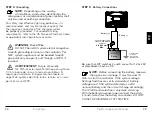
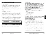
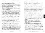
LOAD (+)
LOAD (-)
Fuse or breaker sizing
based on required wire
ampacity
Turn the loads off, and connect the load wires to the
load terminals. DO NOT CLOSE THE FUSE OR
BREAKER AT THIS TIME.
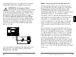
STEP 8:
Power-Up and Verify System Operation
Close the battery disconnect to start the processor,
and activate the controller’s protections. Watch the
charging status, and then the three battery state-
of-charge (SOC) LEDs blink in sequence (G-Y-R),
confirming proper start-up. If they do not light, check
the battery polarity (+/–) and battery voltage.
The green, yellow or red LED will light depending on
the battery state-of-charge (SOC). Confirm that one of
these LEDs is on before going to the next step.
Close solar disconnect. If the solar input is connected
while in sunlight, the charging LED indicator will light.
Confirm proper connection by observing the charging
LED.
Insert the load fuse, or close the breaker, and turn the
load on to confirm a proper connection. If the load does
not turn on, it could be for various reasons: the ProStar
is in LVD (red LED on); there is a short circuit in the load
(LEDs blinking R/G – Y); there is an overload condition
(LEDs blinking R/Y - G); the load is not connected, not
working, or turned off. After all connections have
been completed, observe the LEDs to make sure the
controller is operating normally for system conditions.
If the optional digital meter is used, observe that the
display is scrolling with proper voltage and current
values. Also, a self- test can be performed with digital
meter units.


