


Installation
ProStar Operator’s Manual
29
28
3.0
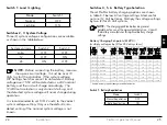
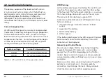
3.4 Wiring
To battery (+) and
(-) terminals for
Not used in this illustration
voltage sensing
To battery for
temperature
sensing
To battery (+)
and (-)
terminals
To load (+)
and (-)
terminals
To properly
sized array
1
4
6
7
2
3
5
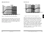
REFER TO FIGURE 3.3 WHEN USING THE FOLLOWING
WIRING INSTRUCTIONS
Figure 3-3. Wiring the ProStar
STEP 1: Check Controller Limitations
Verify that the highest temperature compensated solar
array open-circuit voltage (Voc), and load current do
not exceed the ratings of the ProStar version being
installed.
Multiple controllers can be installed in parallel on the
same battery bank to achieve greater total charging
current. In this type of system, each ProStar must have
its own solar array. The load terminals of multiple
controllers can only be wired together if the total load
draw does not exceed the nameplate current of the
LOWEST rated controller.
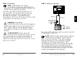
STEP
2: Battery Voltage Sense Wires
WARNING: Fire Hazard
When connecting Battery Sense Wires, install a
5 Amp fuse in the (+) sense wire, six inches
from the (+) battery terminal.
AVERTISSEMENT :
Risque d'incendie
Lors de la connexion des câbles de détec-
tion de batterie, installez un Fusible de 5 A dans le
fil de détection (+), à six pouces de la borne (+) de la
batterie.
Due to connection and cable resistance, voltage drops
are unavoidable in power cables that carry current,
including the ProStar battery cables. If Battery Sense
wires are not used, the controller must use the voltage
reading at the battery power terminals for regulation.
This voltage will be higher than the actual battery bank
voltage while charging the battery.


