44
MSD Multi-Axis System Operation Manual DC-AC Servo Drive
G393-045/G397-053 (Size 5) to G393-170/G397-210 (Size 6A)
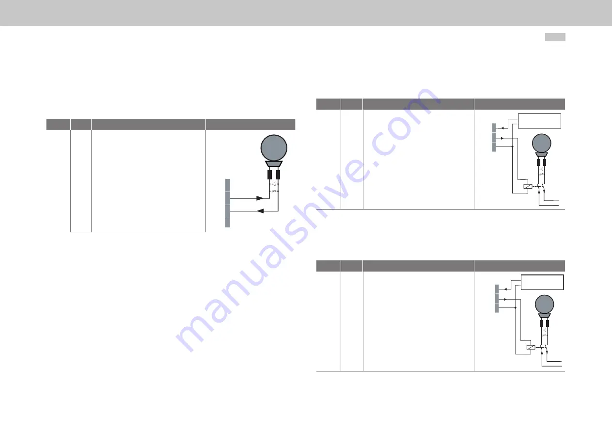
The connector X20 is intended to be used to connect a motor brake.
Des.
Term.
Specification
Connection
+24 V
OSD03
GND
X20/1
X20/2
X20/3
• Short circuit proof
• External power supply
24 V DC (I
IN
= 2.1 A) required
• For operating a motor holding brake up to
I
BR
= 2.0 A maximum, for brakes with a
higher current requirement a relay must be
connected in between
• Overcurrent causes shutdown
• Configurable cable break monitoring
<200 mA in state "1" (up to the relay)
X20
M
Brake (+)
Brake (-)
+24 V DC
+24 V DC 1
OSD03 2
GND 3
+24 V DC power supply
for brake (I
IN
= 2.1 A)
Table 4.8 Specification of the terminal connections X20
G397-250 to G393-450 (Size 7)
The connector X44 is intended to be used to connect a motor brake.
Des.
Term.
Specification
Connection
+24 V
OSD03
GND
X44/5
X44/6
X44/7
• Short circuit proof
• External power supply
+24 V DC (I
IN
= 2.1 A) required
• For operating a motor holding brake up to
I
BR
= 2.0 A maximum, for brakes with a higher
current requirement a relay must be connect-
ed in between
• Overcurrent causes shutdown
• Configurable cable break monitoring <200 mA
in state "1" (up to the relay)
X44
M
Brake (+)
Brake (-)
+24 V DC
+24 V DC 1
OSD03 2
GND 3
+24 V DC power supply
for brake (I
IN
= 2.1 A)
Table 4.9 Specification of the terminal connections X44
4.8.2
Brake driver
G393-004 (Size 1) to G393-032/G397-035 (Size 4)
The connector X13 is intended to be used to connect a motor brake.
Des.
Term.
Specification
Connection
+24 V
BR+
BR−
GND
X13/1
X13/2
X13/3
X13/4
• Short circuit proof
• Power is supplied via the control supply U
V
on
X9 or X10
• U
BR
= U
V
-∆U` (∆U` typically approx. 1.4 V)
• For operating a motor holding brake up to
I
BR
= 2.0 A maximum, for brakes with a
higher current requirement a relay must be
connected in between.
• Overcurrent causes shutdown
• Can also be used as configurable digital
output.
• Configurable cable break monitoring
<500 mA in state "1" (up to the relay)
M
Brake (+)
Brake (-)
X13
1
BR+ 2
BR- 3
4
Table 4.7 Specification of the terminal connections X13
moog
Id. no.: CA97554-001 0
5
/2017
4 Electrical installation
Содержание G393-004
Страница 1: ...moog MSD Servo Drive Operation Manual DC AC Servo Drive Multi Axis System with sinusiodal regeneration...
Страница 62: ...62 MSD Multi Axis System Operation Manual DC AC Servo Drive moog Id no CA97554 001 05 2017 5 Commissioning...
Страница 66: ...66 MSD Multi Axis System Operation Manual DC AC Servo Drive moog Id no CA97554 001 05 2017 6 Diagnostics...
Страница 111: ...MSD Multi Axis System Operation Manual DC AC Servo Drive moog Id no CA97554 001 05 2017 111...


