D661-...G D661-
...P...A/B
D661-...S and H
D661-...P...F/G
5
c.
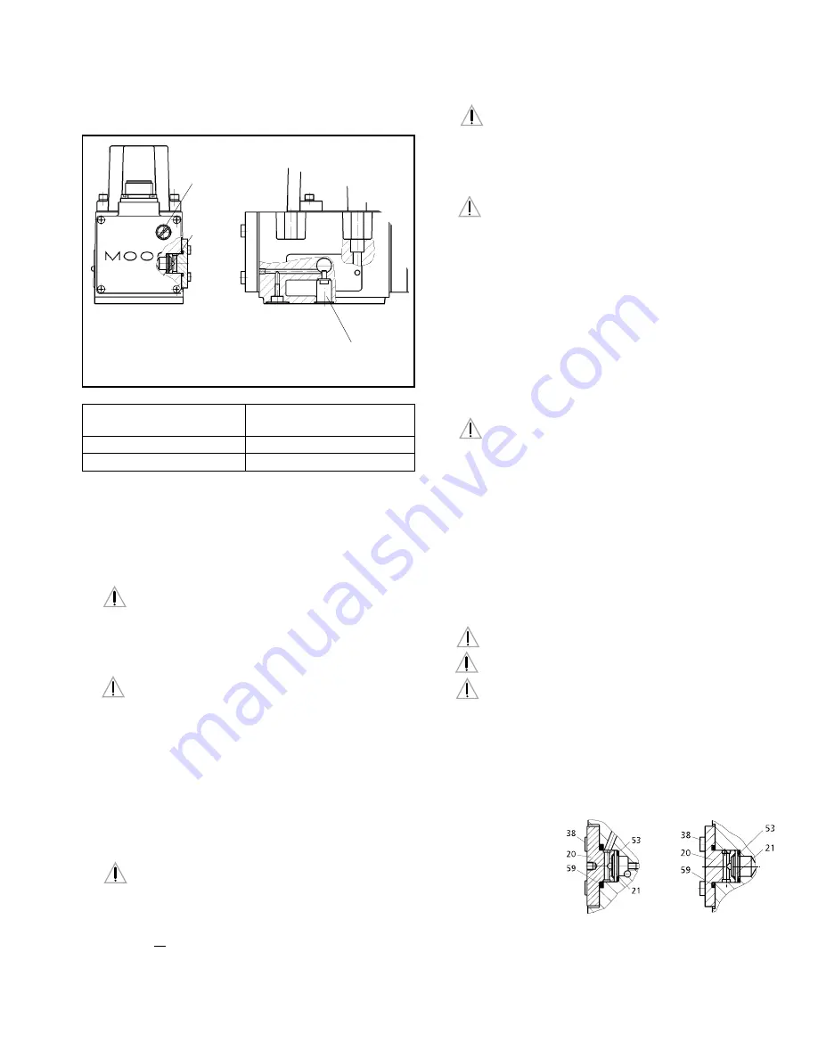
Conversion instruction for Servovalves D661-S, H and P...F/G
screw plug
M4 x 8 DIN 6912-8.8
with metal sealring
U4,5-7-1
Filter
Electric
Nulladjust
(behind screw plug)
X
P
Pilot Flow
Screw Plug
Supply
In Port
Internal P
X
External X
P
5. SETTING UP
This information is valid for new installations to be put into operation
as well as for repair cases.
Filling the Hydraulic System
New oil is never clean. Therefore, the system should generally be
filled by using a filling filter.This fine mesh filter should at least comply
with the following requirement: ß
10
≈
75 (10
µ
m absolute).
Flushing the Hydraulic System
Before the hydraulic system is put into operation for the first
time (also after modifications), it has to be flushed carefully
according to the instructions of the manufacturer of the plant / machine.
a.
Before flushing, suitable flushing elements have to be inserted in the
pressure filters instead of the high pressure elements.
b.
Before flushing, the operational temperature of the hydraulic system
should be achieved. Observe temperature!
c.
A flushing plate or, if the system allows, a directional valve should be
mounted in place of the Moog porportional valve. The P- and T-
connections are flushed through the flushing plate. The user A- and B-
connections can also be flushed by the directional valve.
Attention: The directional valve can lead to unpermissable
movements in the load (i.e. with parallel drives), which may result
in damage of the plant / machine. Instructions of the manufacturer have
to be strictly observed.
Minimum flushing time t can be calculated as follows:
d.
The flushing process can be considered completed when a system
cleanliness of 15/12 according to ISO 4406 or 6 according to NAS
1638 or better is achieved. A long life of the metering lands of the
proportional valve can be expected for this cleanliness class.
V = content of reservoir [gallons]
Q = flow rate of the pump [gpm]
ATTENTION
ATTENTION
DANGER
ATTENTION
ATTENTION
t =
V
• 5
Q
e.
Replace flushing elements in the pressure filters by suitable high
pressure elements after flushing. Install Moog proportional valve
instead of flushing plate or directional valve.
Setting Up
a.
Set up machine/plant according to the operation instructions of
the manufacturer after the valves have been installed. Vent hydraulic
system!
b.
The safety instructions of the machine/plant manufacturer must be
observed. Especially the safety requirements for machines like injection
molding machines (EN 201), blow molding machines (EN 422) and die
casting machines (EN 869), to name a few, are important.
c.
Observe oil temperature.
d.
Check hydraulic system for external leakage!
6. MAINTENANCE
Besides regular visual inspection for external leakage and filter
replacement, maintenance work at the D661 Series valves is not
required.
Explosion proof valves D661K... must not be opened by the
customer! Unauthorized opening will invalidate the explosion proof
approval! Return failed valve to the factory.
Moog valves can only be repaired at Moog Service Centers (for addresses
see back page of this operation instructions).
Filter Replacement
The built-in filter disk protects orifices and nozzles against coarse
contaminants. With severe contamination, the valve response will be reduced.
Replace filter!
Cleaning the filter is useless and may be dangerous!
Before starting to work on the valve, clean the external surface
around the filter cover!
Attention: The filter disk (21) flows from inside to the outside.
After removal of the cover (20) any contamination particles are on the inside
of the disk (21) and therefore, cannot be seen from outside.
a.
Remove four internal hex bolts (38) using Allen wrench (3 mm). Remove
cover (20). Remove the filter disk (21) now accessible by using a scriber
or a fine screwdriver as extraction tool.
b.
Check o-rings (59) and
(53) for damage.
Replace if
necessary.
c.
Insert o-ring (53) first. Then insert the new filter disk (21) such that the
side with the notch at the rim points outward. Mount o-ring (59) on
the cover (20) using clean grease, and mount cover to the valve body.
Torque the four bolts (38) to 4 Nm (35 in-lb).
d.
Check valve for external leakage after pressurizing it.
ATTENTION
ATTENTION
ATTENTION
ATTENTION


